Oil filter unit

a technology of oil filter unit and filter medium, which is applied in the direction of moving filter element filter, filtration separation, separation process, etc., can solve the problems of high manufacturing process requirements, substantial restrictions, and complex seals of replacement filter elements, so as to reduce the differential pressure of filter medium, simple and economical production, and increase the dirt holding capacity

Active Publication Date: 2006-08-17
MANN HUMMEL GMBH
View PDF17 Cites 38 Cited by
  • Summary
  • Abstract
  • Description
  • Claims
  • Application Information

AI Technical Summary

Benefits of technology

[0012] An advantage of the invention is that it substantially enlarges the dirt holding capacity while reducing the differential pressure of the filter medium and keeping the installation space identical. This ensures adequate dirt holding capacity for the coarse and fine particles that occur, so that no additional oil filter is necessary. The use of a frame that is firmly connected with the filter medium ensures a seal between the filter element and the housing which is simple and economical to produce. Because of the large filter surface, the pressure loss is low, such that the filter can be disposed on the inlet side and it is unnecessary to have a fine filter on the pressure side.
[0013] In accordance with one advantageous embodiment of the invention, the filter medium is made of a fully synthetic nonwoven material or of glass fibers. Fully synthetic nonwoven materials are well suited for a comparatively coarse filtration fineness. If finer particles need to be filtered, glass fiber media may be used. High demands with regard to filter fineness can be met by using either glass fiber or nonwoven media. Because of the high melting point of the media, the filter frame can be injection molded around them without problems. As a result, an oil filter with a high degree of filter fineness can be simply and economically manufactured, and a highly effective filtration capacity is assured.
[0014] In a further advantageous embodiment, the use of glass fiber media enables a filter fineness with a pore size of less than 25 μm. The resulting filter fineness makes it possible to further increase the filtration capacity without an additional filter unit.
[0015] In yet another advantageous embodiment, the filter medium is stabilized against the flow pressure by adding a support grid on the inflow and / or the outflow side. This support grid directly contacts the inflow and / or outflow side of the filter medium and extends parallel to the zigzag pleats. The purpose of the support grid is to mechanically stabilize the filter medium against the inflow pressure of the oil and to prevent any fiber particles from being flushed out of the medium. The support grid can furthermore stabilize the fold geometry of the filter medium or can itself form the fold geometry. The material used for the support grid is preferably metal, but a thermostable synthetic resin or a stable spunbound material may also be used. On the lateral faces of the medium, the grid mesh may be injection molded into the frame to ensure reliable mounting.
[0016] The support grid is a simple and reliable way to impart mechanical stability to the filter medium, such that the medium itself requires little stability, can be suitably designed and economically manufactured.
[0017] In accordance with yet another advantageous embodiment, the housing is made of two shells, such that a parting plane extends in a longitudinal direction of the filter housing between an upper shell and a lower shell. The parting plane preferably separates the housing along a horizontal plane and surrounds the filter medium completely. Thus, laterally reversed parting surfaces exist on the upper and lower shell. In the assembled state, the seal contours of the frame cooperate with the parting surfaces and are sealingly connected by the parting surfaces. The seal contours of the frame can thus be disposed in the parting plane. To stabilize this connection, the housing walls may be reinforced or expanded in width by forming a bead along the parting surfaces. The parting surfaces may be clamped together, for example by screws or clip connections, to create a compression force with the seal contours of the element. The seal contour may extend sandwich-style across the entire area of the separation face or may be integrated in a stepped seal profile formed by the parting surfaces.

Problems solved by technology

A disadvantage of this design is that because of its replaceability, the replaceable filter element must have a complex seal relative to the housing at its opposite end faces.
Producing these contours places high demands on the manufacturing process.
Furthermore, the size of the filter surface depends directly on the circumference of the filter chamber, which implies a substantial restriction with regard to the adjustment between dirt holding capacity and filter fineness.
Because of this restriction, the described oil filter assembly cannot be used with a filter medium that ensures the filter fineness required for the operation of automatic transmissions.

Method used


Image

  • Oil filter unit
  • Oil filter unit
  • Oil filter unit

Examples


Embodiment Construction

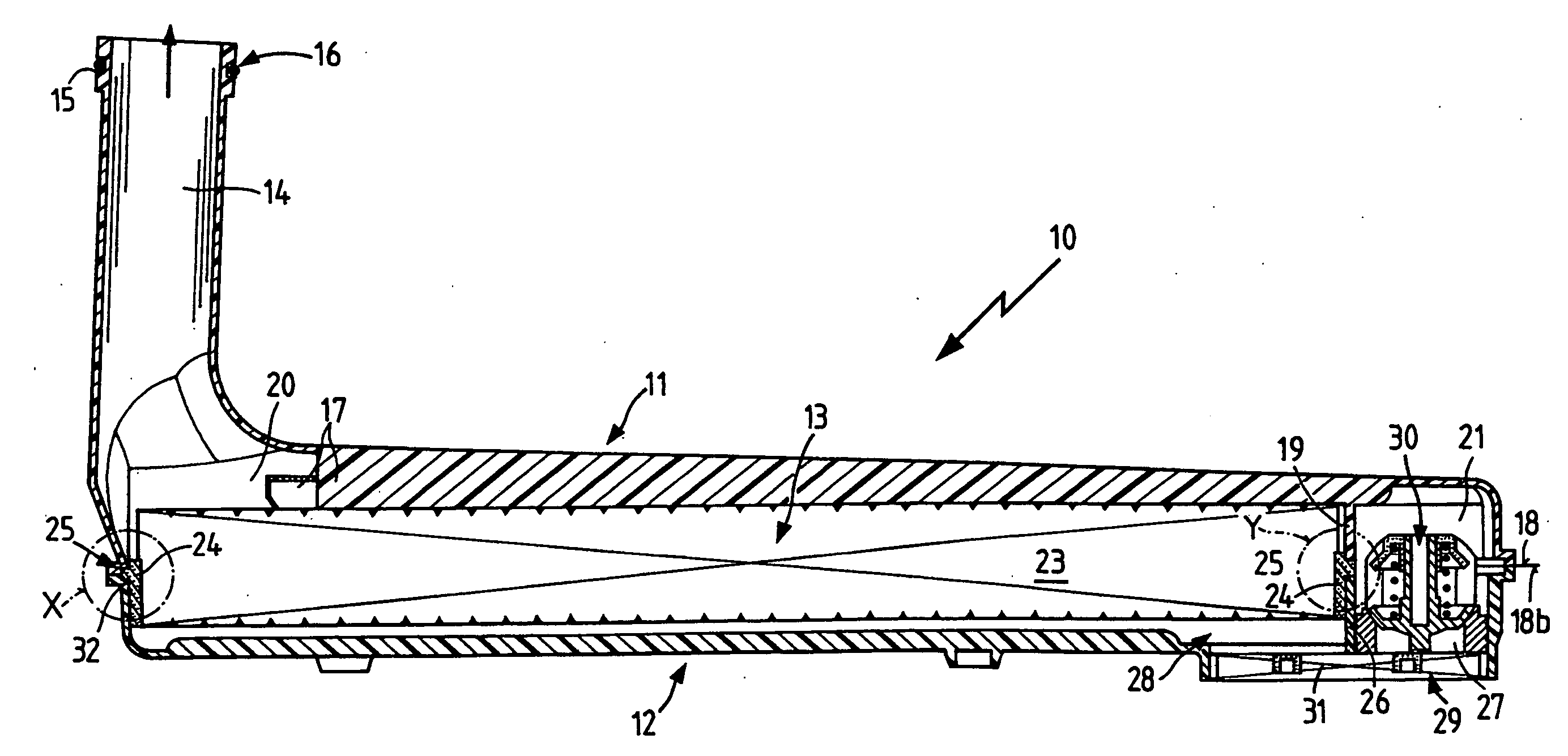
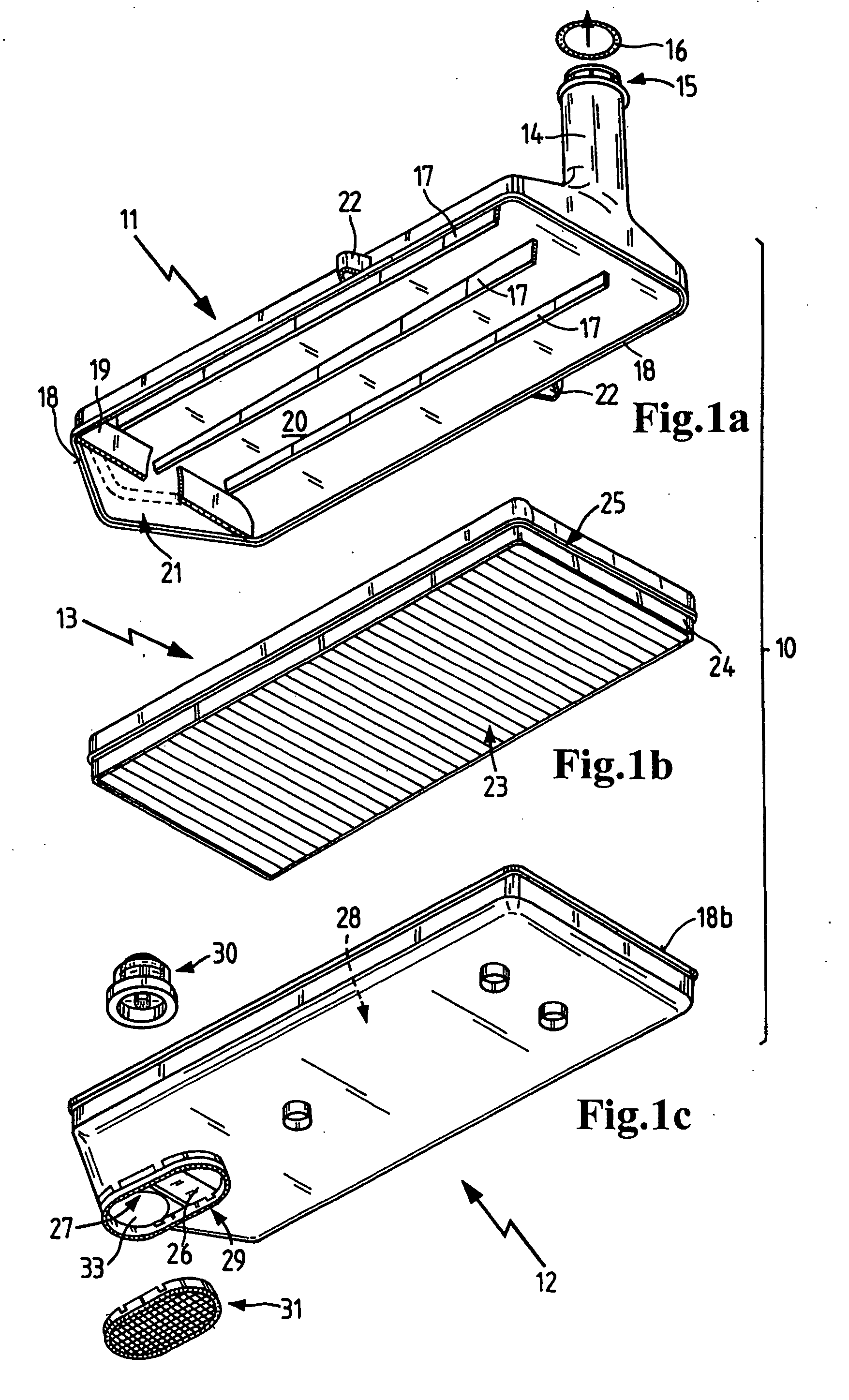
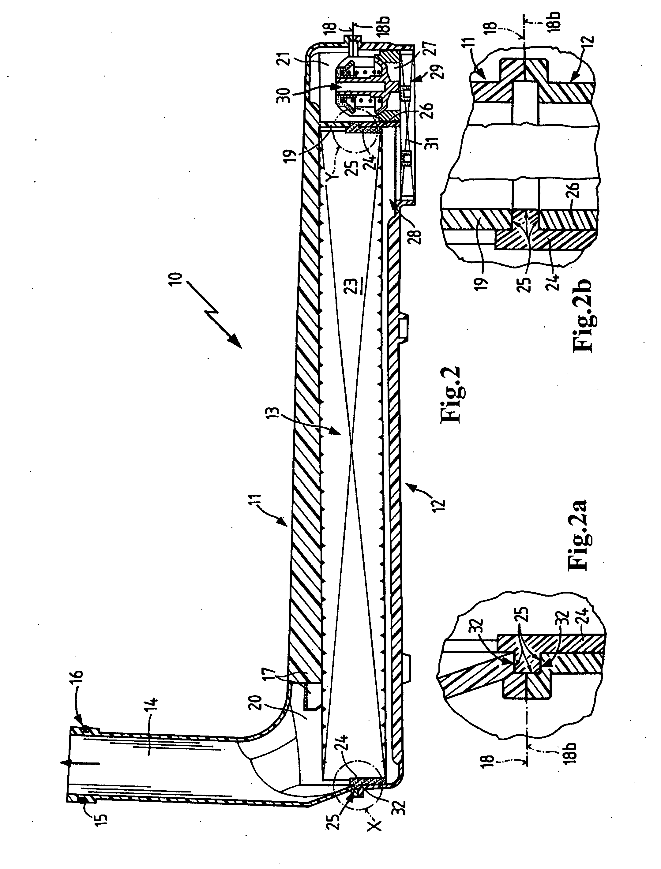
[0037]FIGS. 1a to 1c show an exploded view of an oil filter unit 10 with the individual components disposed in assembly direction. Between an upper shell 11 shown in FIG. 1a and a lower shell 12 shown in FIG. 1c is disposed a filter element 13 depicted in FIG. 1b. A bypass valve 30 and a prefilter 31 are connected to the lower shell 12 when the unit is assembled (FIG. 2).

[0038] The upper shell 11 forms one housing section of the two-part housing. On the upper side, it has a tubular oil outlet fitting 14, on the discharge end of which there is a radial groove 15 to receive an O-ring 16. In longitudinal direction of the upper shell 11, on the lower side facing the filter element 13, fins 17 are formed which stiffen the upper shell 11 and form a support for the filter element 13 as illustrated in the assembled state shown in FIG. 2. The lower pan-shaped opening of the upper shell 11 is enclosed by the flat parting surface 18 along its entire periphery. Within the upper shell 11, a sup...


PUM

PropertyMeasurementUnit
pore sizeaaaaaaaaaa
pressureaaaaaaaaaa
sizeaaaaaaaaaa

Abstract

An oil filter unit for arrangement in the oil sump of an oil circuit, particularly in an automatic transmission. The oil filter unit has a multi-part filter housing with a filter chamber disposed therein such that an oil inlet and an oil outlet communicate with the filter chamber. A filter element is sealingly mounted in the housing between the oil inlet and the oil outlet. The filter element has a pleated filter medium, which is sealingly enclosed by a frame, and the frame has seal contours designed to cooperate with the contours of the filter housing.

Description

BACKGROUND OF THE INVENTION [0001] The present invention relates to an oil filter unit, which is disposed in an oil collection chamber, such as an oil pan or a housing. Oil filter units of this type are used, for example, to filter the lubricating oil of gears, e.g., automatic transmissions. To adapt the filter unit to the space available for installation, it is designed in the shape of a pan and can be positioned directly within the oil sump. The purpose is to separate impurities from the lubricating oil and thereby to increase the life of the lubricating oil and minimize the wear of the unit to be lubricated. The oil filter unit should have the greatest possible filter fineness and minimum flow resistance and at the same time adequate dirt holding capacity and, in motor vehicles with automatic transmissions, should be designed to last for the life of the vehicle. [0002] Published US patent application no. US 2002 / 0121473 A1 (=EP 1,238,693) discloses an oil filter assembly having a...

Claims


Application Information

Patent Timeline
Patent Type & Authority Applications(United States)
IPC IPC(8): B01D35/28
CPCB01D35/0273F01M2011/0029F16H57/0404
Inventor HUEPPCHEN, CLAUDIAROHRMEIER, JOSEFAMESOEDER, DIETEREPLI, SVENNICOLAS, AUDE
Owner MANN HUMMEL GMBH
Why Eureka
Try Eureka