Seal assembly and rotary machine containing such seal

a technology which is applied in the field of sealing assembly and rotary machine containing such seals, can solve the problems of reducing the service life of the seal, and reducing so as to reduce the force imposed by the rub engagement on the rotating component, the effect of reducing the cos

Inactive Publication Date: 2009-08-25
CMG TECH
View PDF69 Cites 40 Cited by
  • Summary
  • Abstract
  • Description
  • Claims
  • Application Information

AI Technical Summary

Benefits of technology

[0013]In accordance with the invention a seal assembly is provided that has a number of seal members or “leaf” seals. The seal assembly may be manufactured from rolled shim stock using wire electro-discharge manufacturing (EDM) to make narrow, precision slots to produce the desired seal member geometry. The seal members may be angled between their free ends and their fixed ends and may include a support for supporting the angle. The invention provides similar benefits as brush seals and finger seals in rotary machine applications but at lower cost and with more robust attributes. Seal member geometry is engineered with respect to thickness, width, length, and number of members to meet specific application requirements of differential pressure and anticipated differential motion. The support serves to limit member movement in one direction and withstand differential pressure, while force imposed by a rub engagement on a rotating component is reduced with the elastic flexure of the seal assembly. Seal member end geometry may be shaped to provide a precision diameter and may also incorporate geometry for aerodynamic lift that would minimize wear in those rotor seal applications that anticipate a heavy transient rub.
[0014]In an alternative embodiment, the support may include a curved surface that provides a progressive gap between seal member fixed ends and their end portions under static conditions. As operating differential pressure increases across the seal assembly, leaf seal members deflect, closing the gap with the support causing their free ends to extend inward toward the rotor for a close running clearance. As a prevailing differential pressure across the seal assembly diminishes, e.g., with decreasing rotor speed during a turbine shutdown, the elastically deflected leaf seal member free ends relax and disengage from the rotor because of the leading convex face of the support. The resulting increase in clearance between seal member free ends and the rotor relieves the concurrent differential thermal expansion closure of stator and seal components, which substantially reduces or eliminates sliding friction force and wear of the leaf seal members.
[0016]In another alternative embodiment, seal assembly may include leaf seal members of bimetallic material. Bimetallic seal members changing shape in response to a change in temperature can relieve the affects of a seal rub when bimetallic seal members are arranged to disengage from the rotor with increasing temperature. Frictional heating during a seal rub increases bimetallic seal member temperature as contact is made with the rotor causing the free portions of the seal members to curl away from the rotor thereby reducing applied rub force and associated wear.

Problems solved by technology

Labyrinth seals, therefore, do not maximize machine performance.
Brush seals, however, pose a number of deficiencies.
First, the multistep brush seal manufacturing process is costly.
Second, brush seal bristles do not always maintain a close running clearance because of their inherent inability to withstand long term wear.
Third, brush seals exposed to solid particles are subject to erosion or other deterioration.
Finally, brush seals are also subject to vibration due to movement of the pressurized fluid being sealed.
Therefore, brush seals oftentimes require dampening features.
For instance, each stacked lamination is a solid ring (not segmented) and, therefore, is limited in application to large diameter machines that require installation / replacement without rotor removal.
In addition, the finger geometry provided is provided in a substantially radial plane, which may prevent adequate flexure of the fingers.
In addition to the above-identified problems, brush seals and finger seals operating at close running clearance are subject to rubbing and wear when differential thermal expansion of stator and rotor components eliminates clearance altogether.
For example during a turbine shutdown, the stator component in which a seal assembly is mounted may cool more quickly than the rotor causing the seal assembly to close on the rotor and rub.
The force imposed during such a rub is reduced somewhat with the flexure of brush and finger seal members, but sliding friction nevertheless causes wear and reduces the life of such seals

Method used


Image

  • Seal assembly and rotary machine containing such seal
  • Seal assembly and rotary machine containing such seal
  • Seal assembly and rotary machine containing such seal

Examples


Embodiment Construction

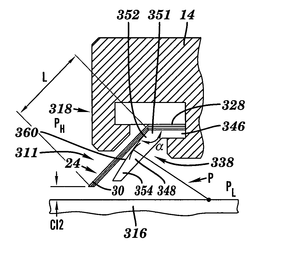
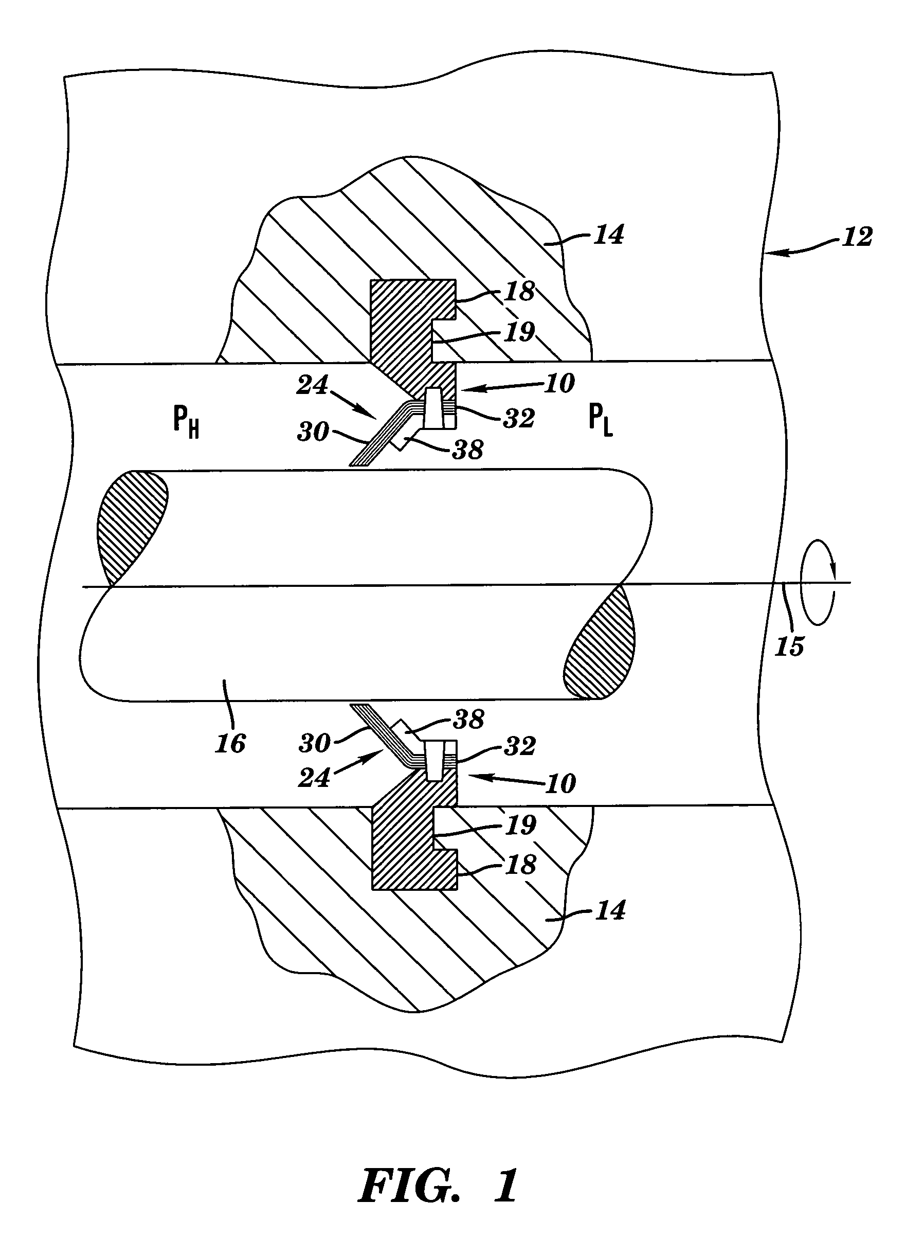
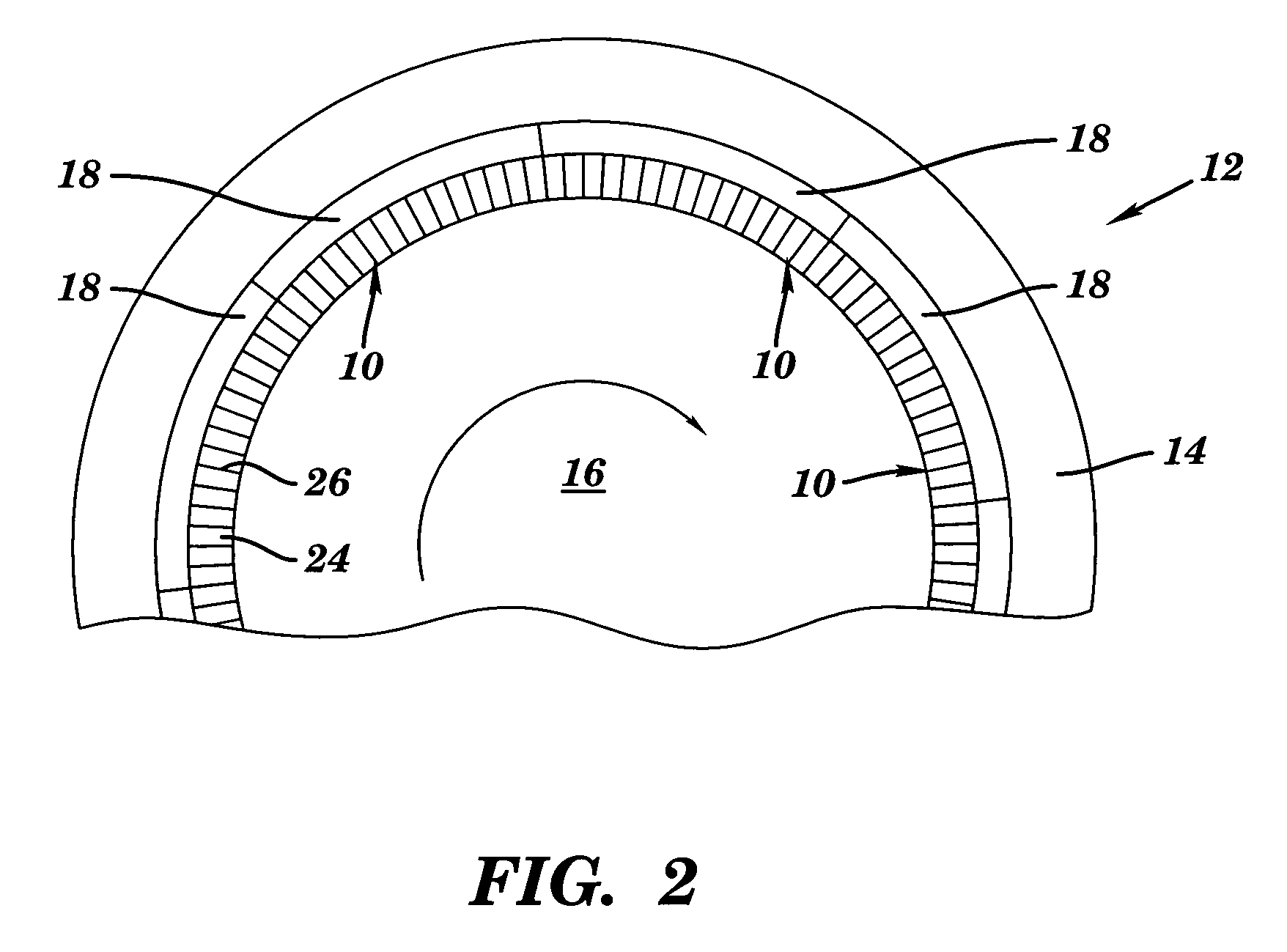
[0049]Referring to FIGS. 1 and 2, the present invention provides a seal assembly 10 for use with a rotary machine 12. Rotary machine 12 may be any well known machinery that includes a non-rotating component 14 and a rotating component 16 having a longitudinal axis 15, e.g., a gas turbine, a jet engine, a steam turbine, etc. For description purposes, the present invention will be described in terms of a steam or combustion (gas) turbine having a stator or stator body 14 and a rotor 16. As shown in FIG. 1, a higher pressure chamber PH and a lower pressure chamber PL are generated during steady state operation of rotary machine 12. Pressure from higher pressure chamber PH is exerted against at least part of seal assembly 10, which acts to seal higher pressure chamber PH from lower pressure chamber PL. FIG. 2 shows an embodiment of rotary machine where a number of arcuate seal assemblies 10 are utilized about rotating component 16.

[0050]Turning to FIGS. 3 and 4, seal assembly 10 include...


PUM


Abstract

A seal assembly which, among other applications, may be used for sealing fluid leakage between a steam or combustion (gas) turbine rotor and a turbine stator body. The seal assembly includes elements having a plurality of spaced leaf seal members with slots therebetween. Each leaf seal member is angled out-of-plane between a fixed end and a free end thereof, and the free ends slidably engage the rotatable component. In one embodiment, the fixed ends of each leaf seal member are positioned substantially perpendicular to a longitudinal axis of the rotating component. A support may be provided supporting the free end such that it contacts a distal end of the support in an operative state and is out of contact with the distal end in an inoperative state. Seal members may include two different materials having different coefficients of thermal expansion.

Description

[0001]This application is a continuation-in-part application of U.S. Ser. No. 09 / 791,248, filed Feb. 23, 2001 now U.S. Pat. No. 6,644,667.BACKGROUND OF THE INVENTION[0002]1. Technical Field[0003]The present invention relates generally to seals for rotary machines and, more particularly, to a seal assembly and rotary machine containing such seal.[0004]2. Related Art[0005]In many rotary machines, such as a gas turbine or jet engine, a gas is compressed in a compressor and mixed with a fuel source in a combustor. The combination of gas and fuel is then ignited for generating combustion gases that are directed to turbine stage(s) that derive energy therefrom. Both turbine stage(s) and compressor have stationary or non-rotating components, e.g., vanes, cooperating with rotating components, e.g., blades, for compressing and expanding the operational gases. The operational gases change in pressure through the machine and a variety of seals are provided to preserve the differential pressure...

Claims


Application Information

Patent Timeline
Patent Type & Authority Patents(United States)
IPC IPC(8): F01D11/02F16J15/44F16J15/447F16J15/32
CPCF16J15/3292F01D11/02F05D2240/56F05D2240/57F05D2250/313F05D2250/314F16J15/3284
Inventor GRONDAHL, CLAYTON M.
Owner CMG TECH
Why Eureka
Try Eureka