Water pump pipe cut-off tool

a technology of water pump and pipe, which is applied in the direction of earthwork drilling, wellbore/well accessories, etc., can solve the problems of system abandonment, significant effort and resources must be expended to restore access quickly, and the system is often left abandoned

Active Publication Date: 2016-11-22
TAYLOR GERYL W +1
View PDF24 Cites 1 Cited by
  • Summary
  • Abstract
  • Description
  • Claims
  • Application Information

AI Technical Summary

Benefits of technology

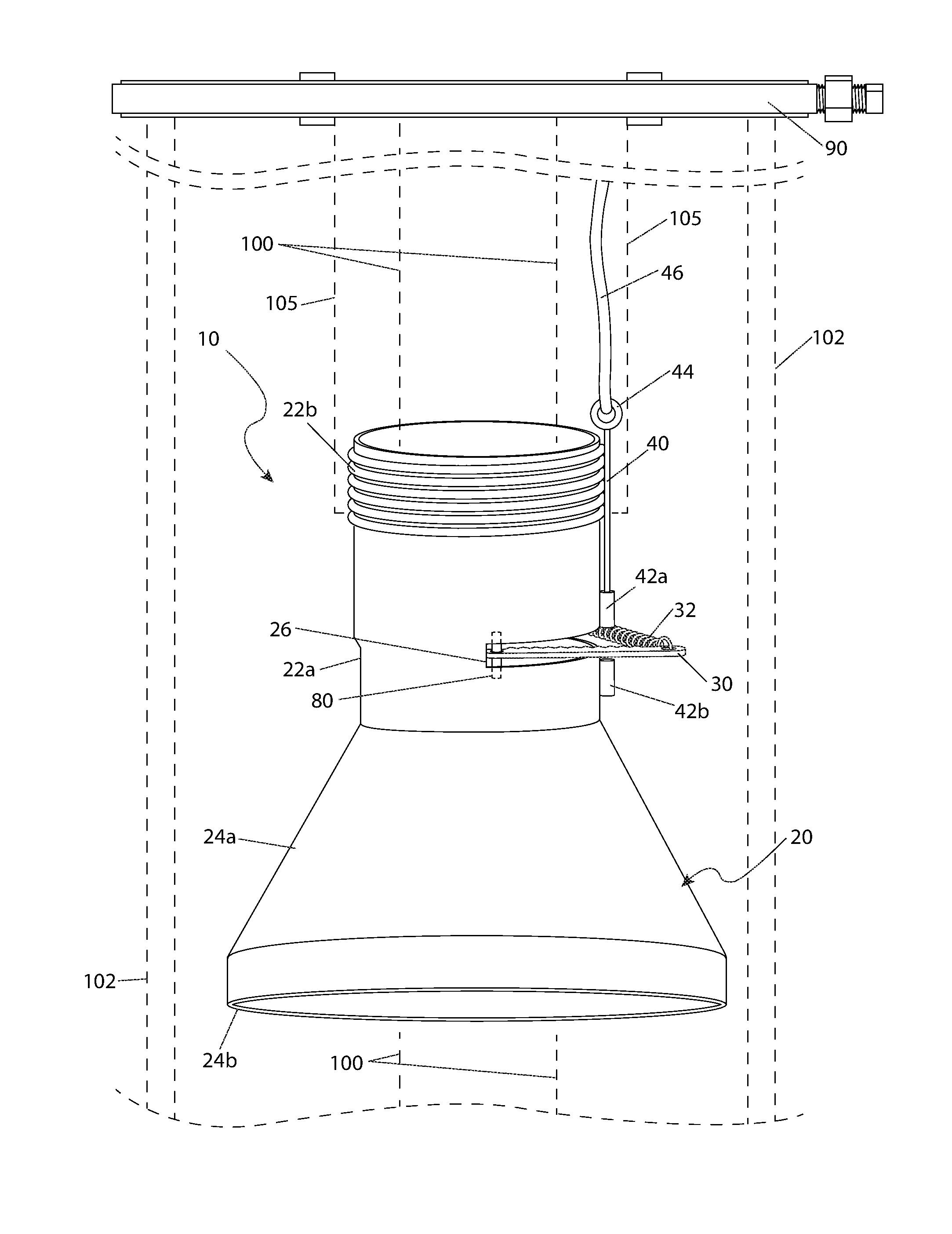
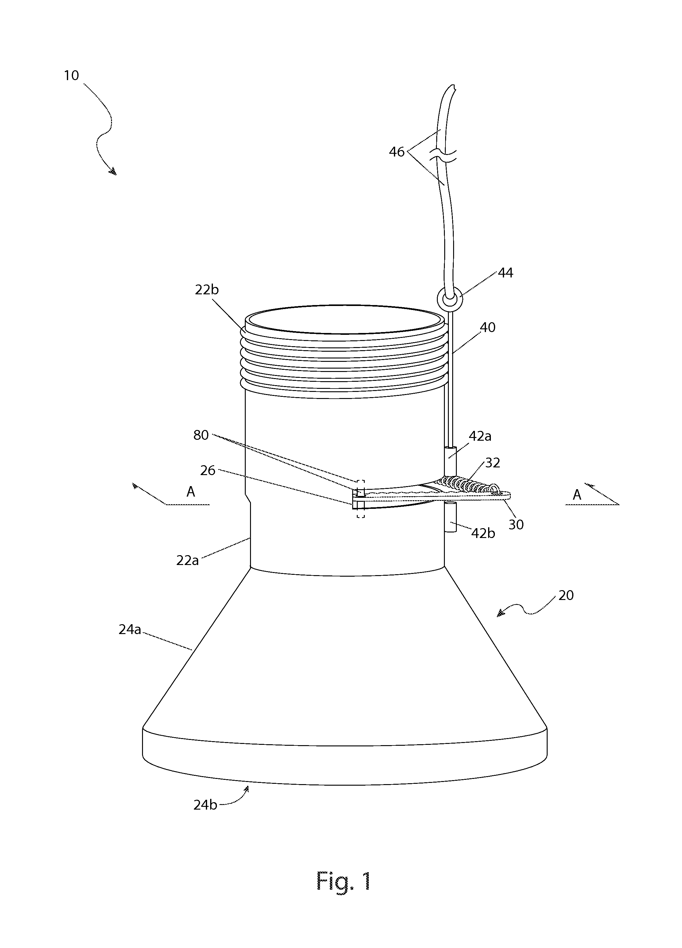
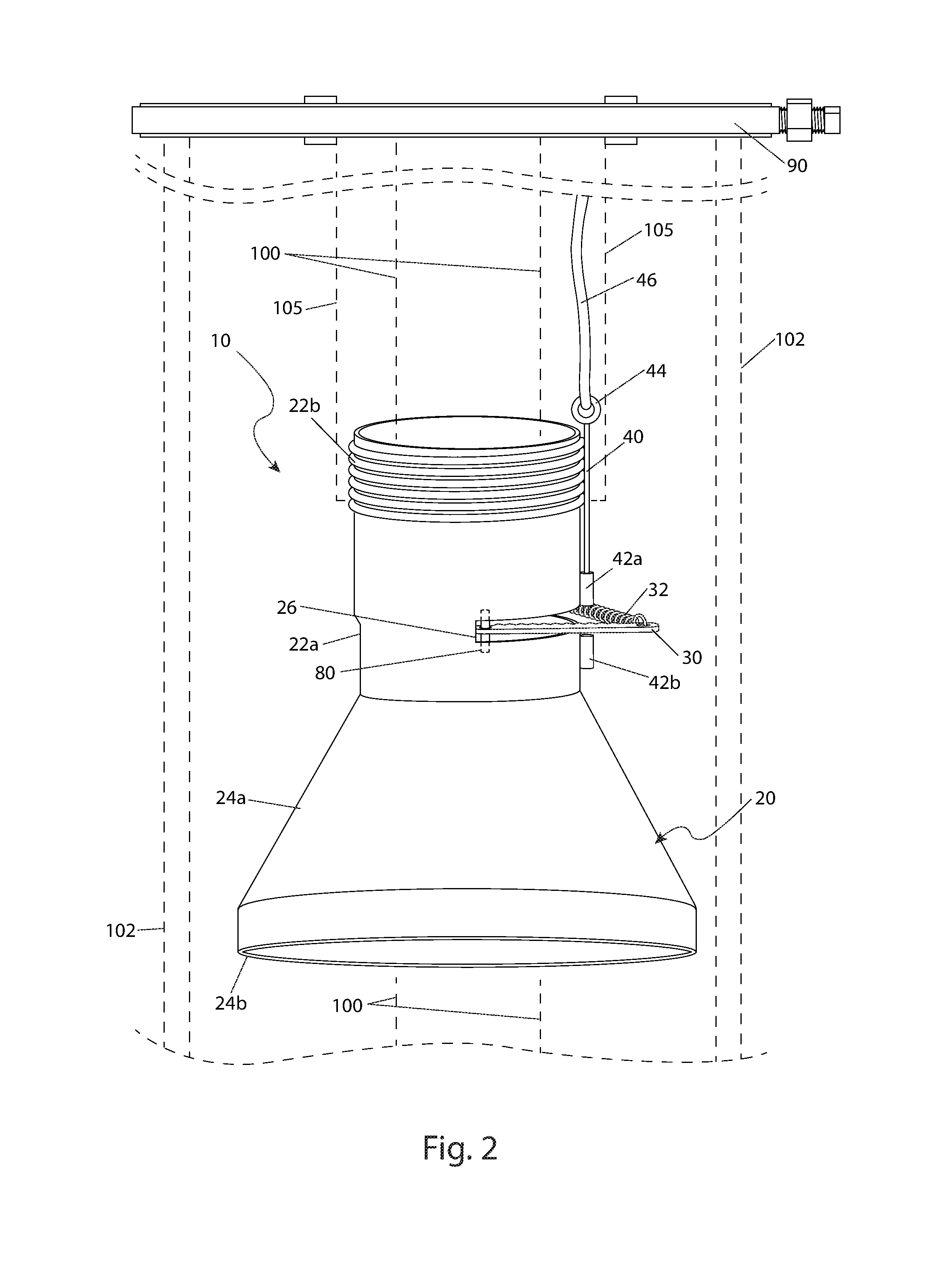
[0006]The apparatus comprises a cylindrical upper section and conical lower section. The upper section is threaded to enable connection to a threaded extraction pipe. The lower section has an outer diameter to allow insertion into a well casing, but an inner diameter to allow reception of an original water pipe of the well. The upper section is further provided with a slot, through which a cutting blade traverses when actuated. The cutting blade is attached to a spring mechanism so as to allow horizontal rotation of the cutting blade. The spring mechanism biases the blade inwardly so as to ensure that the cutting edge of the cutting blade makes contact with the original water pipe. A trigger mechanism, when actuated, retains the cutting blade in an outward position while the extraction pipe and apparatus are inserted into the well.
[0007]The apparatus cuts and retrieves tubing from a water well casing, thereby allowing space for a new pump to be installed into the well. The apparatus is threadingly attached to an end of an extraction pipe. The extraction pipe, along with the attached apparatus, is slid over a damaged pipe within a well. A spring-loaded cutting blade of the apparatus is released via a trigger, thereby allowing the cutting edge of the blade to make contact with the damaged pipe. The extraction pipe, along with the apparatus, is then rotated so that the cutting edge of the cutting blade cuts through the damaged pipe. After the damaged pipe is severed, the cutting blade is positioned to traverse an inner area of the apparatus opening to support the severed pipe within the extraction pipe so that it can be removed from the well. After removal, a new pipe and a new submersible pump are installed above the original submersible pump in a conventional manner.

Problems solved by technology

However, because of their impact on society, minor interruptions in the operability of these technologies can result in destitute and deprivation.
Yet, when an interruption in access to water occurs, significant effort and resources must be expended to restore access quickly.
If the pump or piping of the system fails, the system is often left abandoned due to the cost and time required to correct it.

Method used


Image

  • Water pump pipe cut-off tool
  • Water pump pipe cut-off tool
  • Water pump pipe cut-off tool

Examples


Embodiment Construction

[0036]The best mode for carrying out the invention is presented in terms of its preferred embodiment, herein depicted within FIGS. 1 through 4 and alternately within FIG. 5. However, the invention is not limited to the described embodiment and a person skilled in the art will appreciate that many other embodiments of the invention are possible without deviating from the basic concept of the invention, and that any such work around will also fall under scope of this invention. It is envisioned that other styles and configurations of the present invention can be easily incorporated into the teachings of the present invention, and only one particular configuration shall be shown and described for purposes of clarity and disclosure and not by way of limitation of scope.

[0037]The terms “a” and “an” herein do not denote a limitation of quantity, but rather denote the presence of at least one of the referenced items.

[0038]The present invention describes a water pump pipe cut-off tool (here...


PUM


Abstract

A water pump pipe cutoff tool provides a means to cut and retrieve an existing original water pipe from within an existing well in such cases where a faulty submersible pump is trapped within said well. By cutting and removing the original water pipe, a new submersible pump can be installed into the well, thereby avoiding the expense of drilling a new well.

Description

RELATED APPLICATIONS[0001]The present invention was first described in and claims the benefit of U.S. Provisional Application No. 61 / 743,602, filed Sep. 7, 2012, the entire disclosures of which are incorporated herein by reference.FIELD OF THE INVENTION[0002]The present invention relates to a tool to cut and retrieve a portion of piping within a water well below the ground surface, particularly for replacing a damaged section of piping and / or a submersible pump.BACKGROUND OF THE INVENTION[0003]Socioeconomic factors are of the upmost importance when considering the impact of technological advancement on the general well being of mankind. Technologies that improve a society's socioeconomic status are often times deemed marvels. Such advancements tend to catapult man into the next paradigm shift. However, because of their impact on society, minor interruptions in the operability of these technologies can result in destitute and deprivation. None is more evident than the technologies th...

Claims


Application Information

Patent Timeline
Patent Type & Authority Patents(United States)
IPC IPC(8): E21B29/00
CPCE21B29/00E21B29/007E21B31/16
Inventor TAYLOR, GERYL W.TAYLOR, DAKOTA W.
Owner TAYLOR GERYL W
Why Eureka
Try Eureka