System and method of inputting an intended backing path
What is AI technical title?
AI technical title is built by PatSnap AI team. It summarizes the technical point description of the patent document.
a technology of intended path and display, which is applied in the direction of navigation instruments, steering of trailers, instruments, etc., can solve the problems of many drivers' difficulty in operating vehicles connected to trailers
Active Publication Date: 2016-11-22
FORD GLOBAL TECH LLC
View PDF463 Cites 68 Cited by
Summary
Abstract
Description
Claims
Application Information
AI Technical Summary
This helps you quickly interpret patents by identifying the three key elements:
Problems solved by technology
Method used
Benefits of technology
Problems solved by technology
Operating a vehicle that is connected to a trailer is very challenging for many drivers.
Method used
Image
Click on the blue label to locate the original text in one second.
Reading with bidirectional positioning of images and text.
Examples
Embodiment Construction
[0020]As required, detailed embodiments of the present invention are disclosed herein. However, it is to be understood that the disclosed embodiments are merely exemplary of the invention that may be embodied in various and alternative forms. The figures are not necessarily to a detailed design and some schematics may be exaggerated or minimized to show function overview. Therefore, specific structural and functional details disclosed herein are not to be interpreted as limiting, but merely as a representative basis for teaching one skilled in the art to variously employ the present invention.
[0021]As used herein, the term “and / or,” when used in a list of two or more items, means that any one of the listed items can be employed by itself, or any combination of two or more of the listed items can be employed. For example, if a composition is described as containing components A, B, and / or C, the composition can contain A alone; B alone; C alone; A and B in combination; A and C in com...
PUM
Abstract
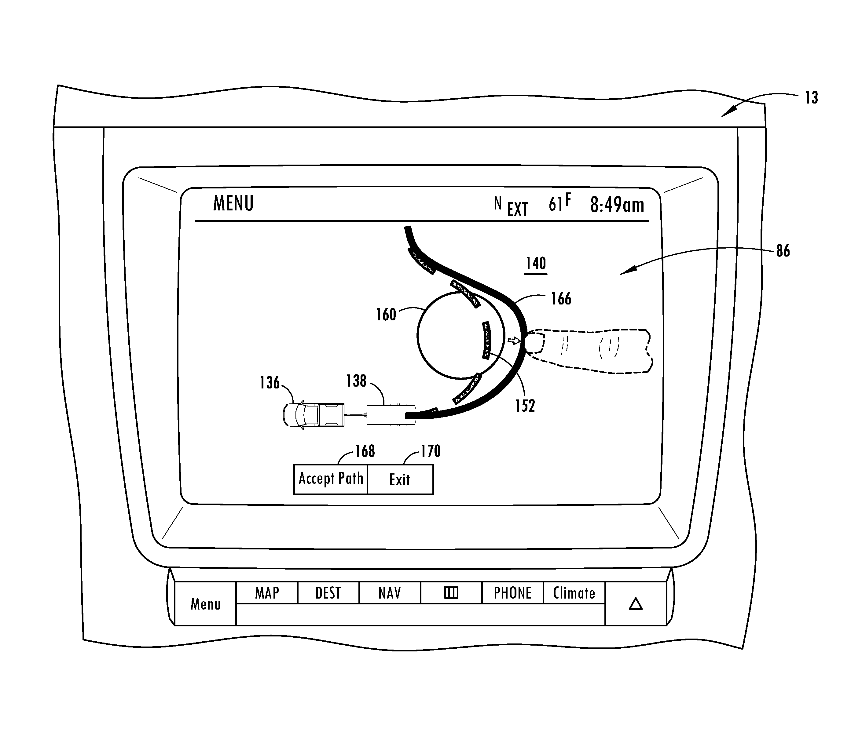
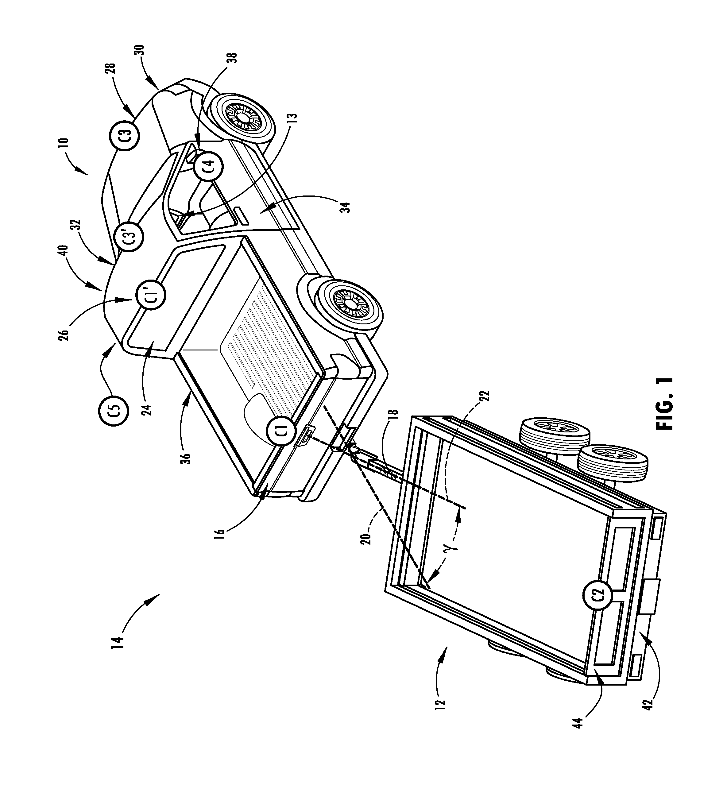
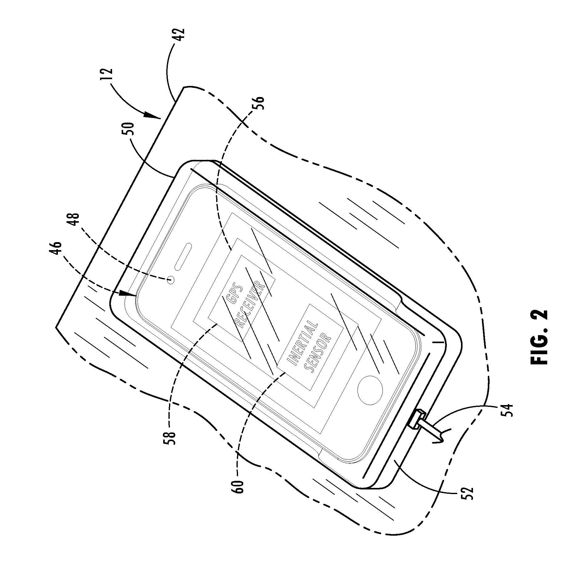
A path input system is provided. The path input system includes at least one imaging device for generating image data. A GPS device is included for generating satellite image data. A controller generates an aerial view of a vehicle and a trailer based on the image data and the satellite data. A display is included for displaying the aerial view and registering a touch event thereon that inputs an intended path for the vehicle and the trailer.
Description
CROSS-REFERENCE TO RELATED APPLICATIONS[0001]This patent application is continuation-in-part of U.S. patent application Ser. No. 14 / 289,888, which was filed on May 29, 2014, entitled “DISPLAY SYSTEM UTILIZING VEHICLE AND TRAILER DYNAMICS,” which is a continuation-in-part of U.S. patent application Ser. No. 14 / 256,427, which was filed on Apr. 18, 2014, entitled “CONTROL FOR TRAILER BACKUP ASSIST SYSTEM,” which is a continuation-in-part of U.S. patent application Ser. No. 14 / 249,781, which was filed on Apr. 10, 2014, entitled “SYSTEM AND METHOD FOR CALCULATING A HORIZONTAL CAMERA TO TARGET DISTANCE,” which is a continuation-in-part of U.S. patent application Ser. No. 14 / 188,213, which was filed on Feb. 24, 2014, entitled “SENSOR SYSTEM AND METHOD FOR MONITORING TRAILER HITCH ANGLE,” which is a continuation-in-part of U.S. patent application Ser. No. 13 / 847,508, which was filed on Mar. 20, 2013, entitled “HITCH ANGLE ESTIMATION.” U.S. patent application Ser. No. 14 / 188,213 is also a co...
Claims
Application Information
Patent Timeline
Application Date:The date an application was filed.
Publication Date:The date a patent or application was officially published.
First Publication Date:The earliest publication date of a patent with the same application number.
Issue Date:Publication date of the patent grant document.
PCT Entry Date:The Entry date of PCT National Phase.
Estimated Expiry Date:The statutory expiry date of a patent right according to the Patent Law, and it is the longest term of protection that the patent right can achieve without the termination of the patent right due to other reasons(Term extension factor has been taken into account ).
Invalid Date:Actual expiry date is based on effective date or publication date of legal transaction data of invalid patent.

