
Single-mode, bend-compensated, large-mode-area optical fibers designed to accomodate simplified fabrication and tighter bends

a technology of optical fibers and bends, applied in the field of large-mode area optical fibers, can solve the problems of reducing the ability of various fiber designs to selectively suppress homs, limiting the scaling area, and reducing the quality of beams, etc., and achieves the effect of low-cost fabrication and easy fabrication

Active Publication Date: 2016-11-29
OFS FITEL LLC
View PDF9 Cites 37 Cited by
  • Summary
  • Abstract
  • Description
  • Claims
  • Application Information

AI Technical Summary

Benefits of technology

This design effectively suppresses higher-order modes and maintains single-mode operation even under tight bends, enabling larger mode areas and reduced bend loss, thus improving the performance of high power optical amplifiers.

Problems solved by technology

However, larger area fibers typically support several or many modes, increasing the likelihood that HOMs will also propagate in the fiber and undergo amplification, thereby degrading the quality of beam.
Bends in the fiber exacerbate this problem they reduce the ability of various fiber designs to selectively suppress HOMs while ensuring propagation of the fundamental mode at power levels that satisfy typical performance requirements.
Macrobend loss is often the dominant source of loss, bend distortion limits the scaling of area, and bends degrade single-mode operation, as noted above, by limiting the degree to which unwanted HOMs can be selectively suppressed.
However, this strategy may be difficult to implement.

Method used


Image

  • Single-mode, bend-compensated, large-mode-area optical fibers designed to accomodate simplified fabrication and tighter bends
  • Single-mode, bend-compensated, large-mode-area optical fibers designed to accomodate simplified fabrication and tighter bends
  • Single-mode, bend-compensated, large-mode-area optical fibers designed to accomodate simplified fabrication and tighter bends

Examples


Embodiment Construction

Bend-Compensated LMA Fibers—General Design

[0069]In this section of the parent application we describe the design of bend-compensated LMA fibers that are configured to be coiled or bent. Thus, at least a longitudinal segment of the LMA fiber is characterized by a bend radius Rb. The coiling or bending of such LMA fibers is often an expedient to save space or satisfy some other physical requirement of a particular application. Typical applications (e.g., optical fiber amplifiers and lasers) will be described in a later section.

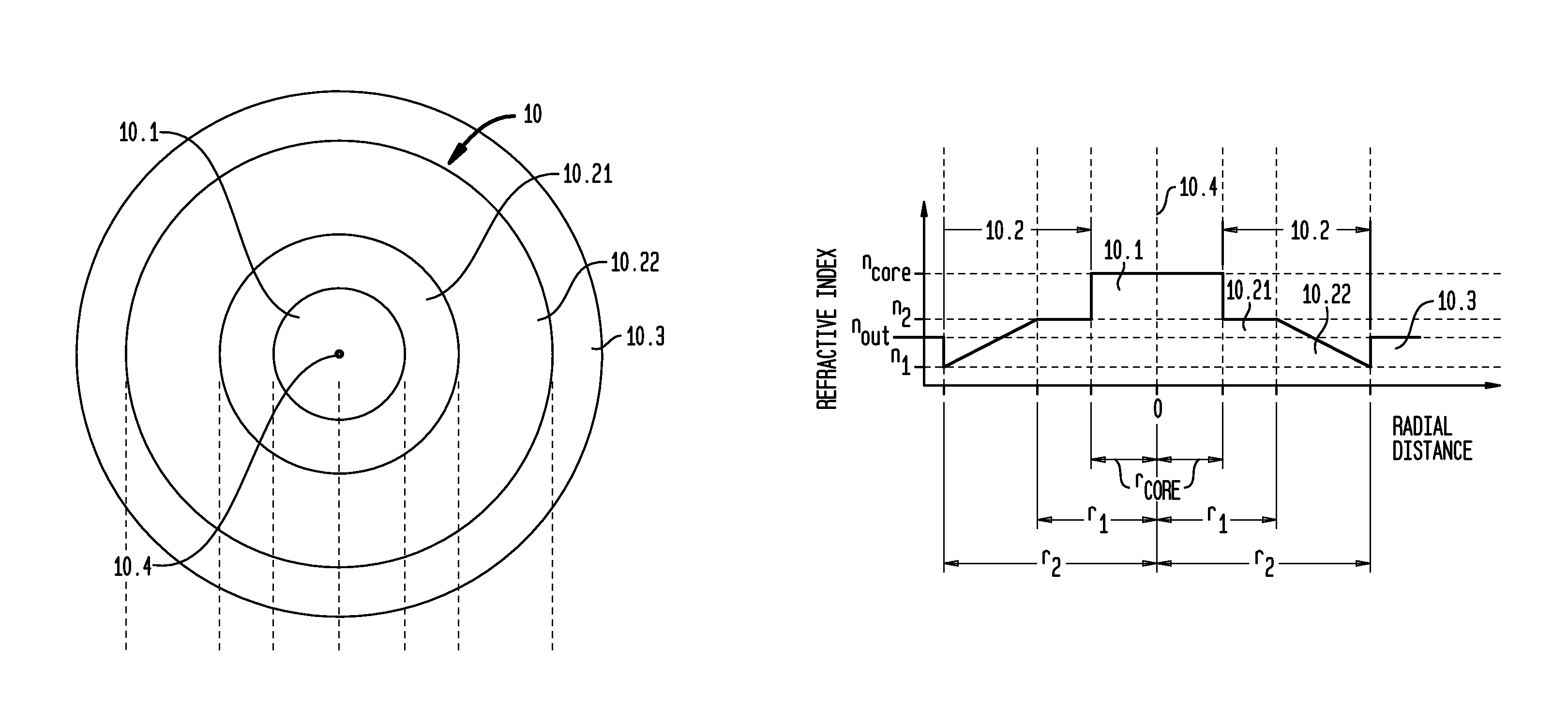
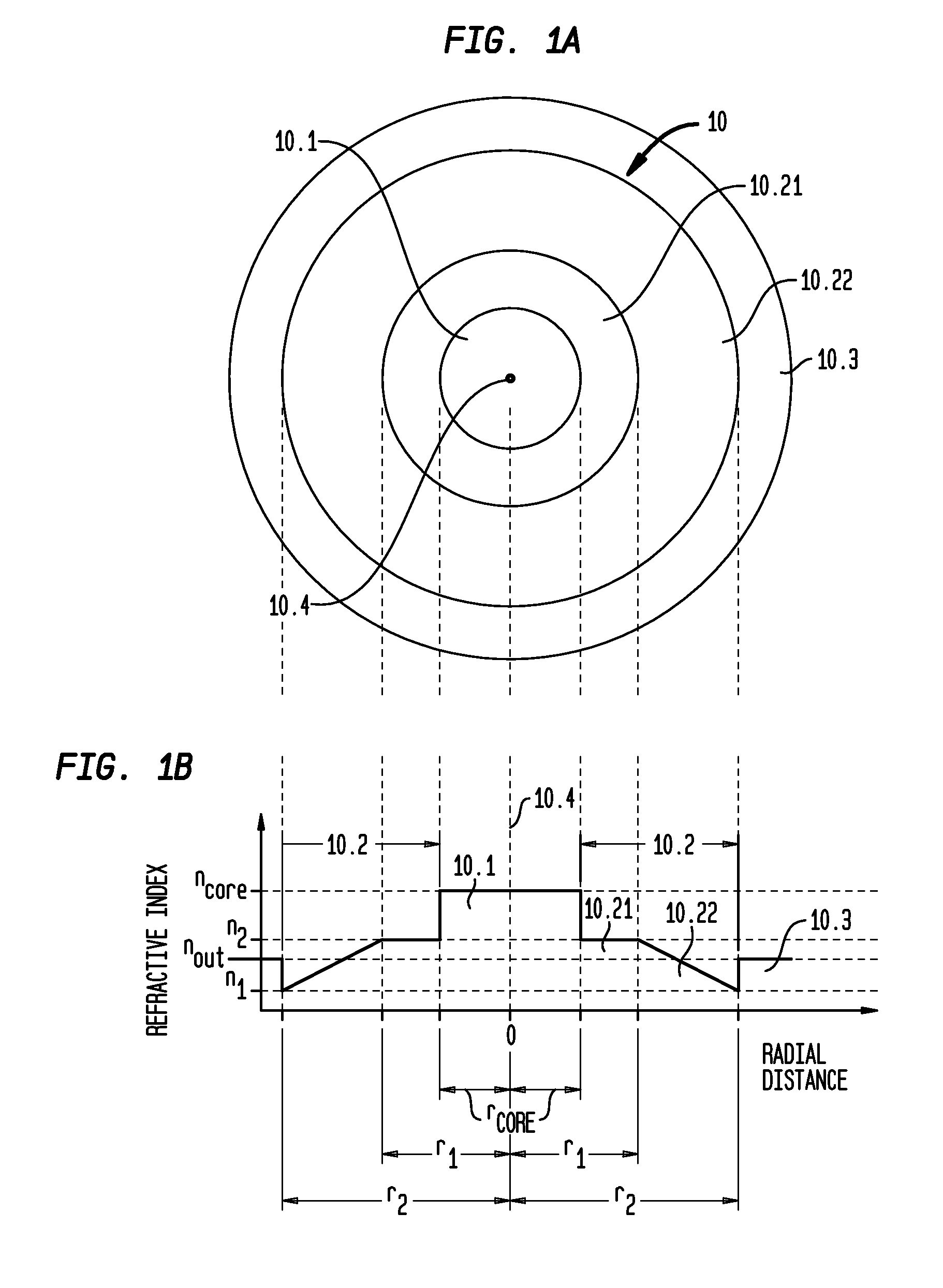
[0070]Turning now to FIG. 1A, we show a transverse cross-section of a bend-compensated, LMA optical fiber 10 in accordance with one aspect of our invention. Fiber 10 comprises a core region 10.1, an annular inner cladding region 10.2 surrounding the core region, and an annular outer cladding region 10.3 surrounding the inner cladding region. In general, these regions are configured to support the propagation of signal light effectively in a single mode (i.e., th...


PUM

PropertyMeasurementUnit
bend diametersaaaaaaaaaa

Abstract

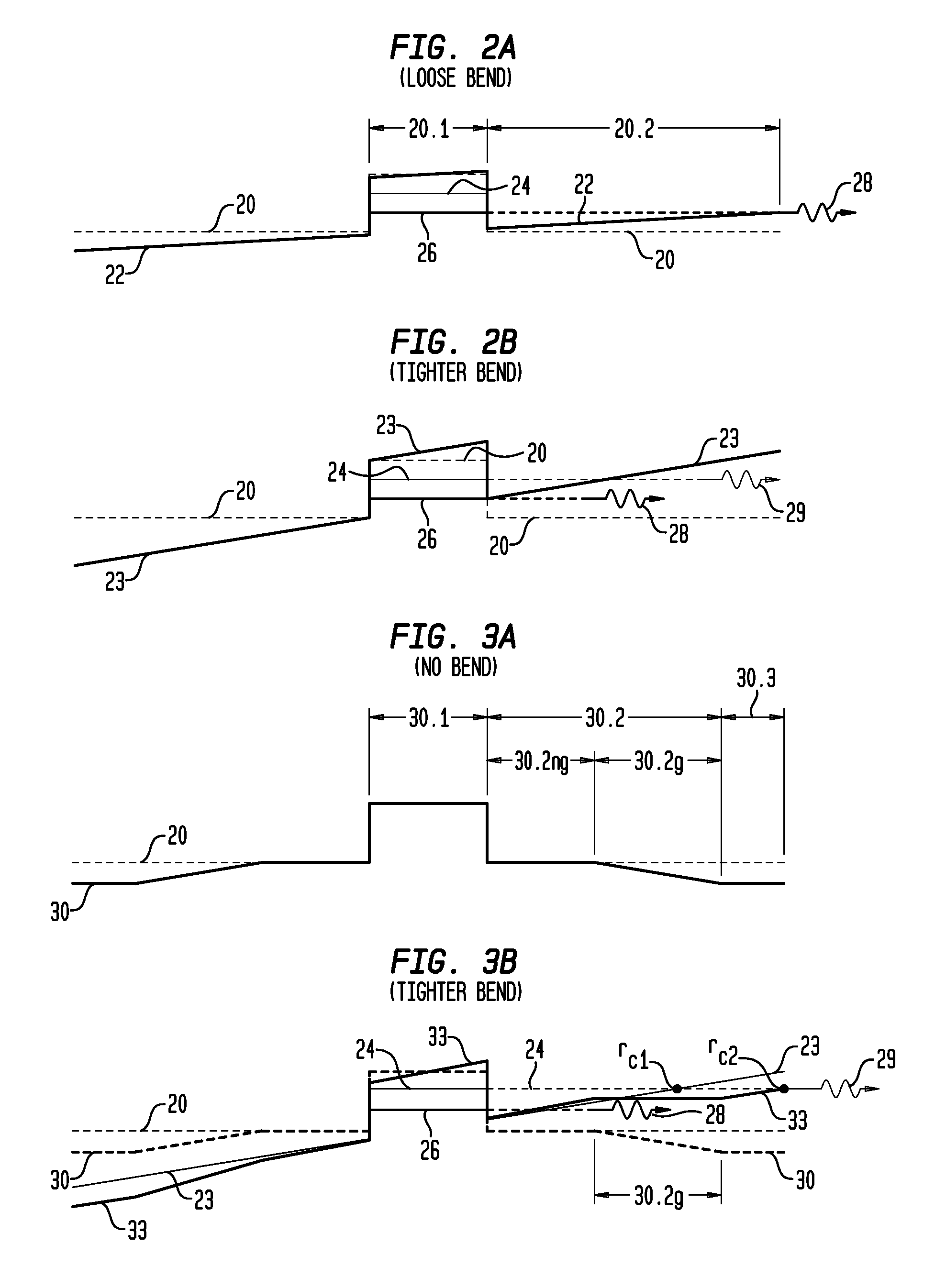
Described is a general strategy of bend-compensated, single-mode LMA fibers extended into a regime with higher total index contrast and where a larger gradient is used to cancel the perturbation of a tighter anticipated bend.

Description

CROSS-REFERENCE TO RELATED APPLICATIONS[0001]This application claims priority from provisional application Ser. No. 61 / 833,445 filed on Jun. 10, 2013 and is a continuation-in-part of parent application Ser. No. 13 / 990,921 (Fini 21-31) filed on May 31, 2013. The parent application claims priority from PCT application No. PCT / US11 / 63351 filed on Dec. 5, 2011 as well as from two provisional applications: Ser. No. 61 / 506,631 filed on Jul. 11, 2011 and Ser. No. 61 / 419,420 filed on Dec. 3, 2010. All of these documents are incorporated by reference herein.BACKGROUND OF THE INVENTION[0002]Field of the Invention[0003]This invention relates to large-mode-area (LMA) fibers designed to compensate for the effects of bends in the fiber and to suppress higher-order modes (HOMs) and, more particularly to high power optical amplifiers that incorporate such LMA fibers.[0004]Discussion of the Related Art[0005]Optical fiber amplifiers have great impact in diverse applications ranging from high power de...

Claims


Application Information

Patent Timeline
Patent Type & Authority Patents(United States)
IPC IPC(8): G02B6/028G02B6/036G02B6/02
CPCG02B6/0285G02B6/02019G02B6/0286G02B6/03633
Inventor FINI, JOHN MNICHOLSON, JEFFREY WTAUNAY, THIERRY F
Owner OFS FITEL LLC
Learn More