Anesthesia Delivery And Ventilation System

a ventilation system and anesthesia technology, applied in the field of anesthesia delivery and ventilation system, can solve the problems of increased cost and disturbance of ventilation patterns, increased risk of negative end-expiratory pressure, and increased risk of gas leakage in conventional cylinder-piston anesthesia delivery system

Active Publication Date: 2018-04-05
KIRURA HLDG BV
View PDF0 Cites 16 Cited by
  • Summary
  • Abstract
  • Description
  • Claims
  • Application Information

AI Technical Summary

Problems solved by technology

A conventional bag-in-box system, also referred to as a bellows system, with a single in-line blower is a complex mechanical system and introduces additional cost and disturbance in ventilation patterns.
Moreover, conventional bag-in-box systems have a single connection for inspiratory section gases and expiratory section gases that preclude complete mixing of the inspiratory section gases and the expiratory section gases, especially in low breathing volumes.
In addition to the costs involved and disturbances in ventilation patterns, conventional cylinder-piston type anesthesia delivery systems are more prone to leakage of gases and pose a high risk of occurrence of a negative end-expiratory pressure, which is a subatmospheric pressure that develops at a patient's airway at the end of expiration.
In these systems, a positive end-expiratory pressure is maintained in a circulating flow of gases by a complex feedback control system based on a set of flow sensors and control of the ventilation valve and the ventilation blower, which results in oscillations or a substantially slow reaction to remove the oscillations.
If the positive end-expiratory pressure valve is inadvertently installed upside down, the anesthesia circulating loop will be completely blocked.
There are several problems associated with the use of a proportional valve, for example, a positive end-expiratory pressure valve, to create a positive end-expiratory pressure in an anesthesia circulating loop.
A positive end-expiratory pressure valve installed in the expiratory section of the anesthesia circulating loop increases the resistance to flow of the gases exhaled by the patient, and increases the breathing effort of the patient especially in low ventilation volumes.
Moreover, the positive end-expiratory pressure valve increases the complexity of a control algorithm for simultaneously controlling the continuous flow of gases and ventilation patterns.
The simultaneous and continuous control of the positive end-expiratory pressure valve and the power to the in-line blower and the ventilation blower increases the risk of an interruption or a lower than an optimal volume of the continuous flow of breathing gases.
Furthermore, the use of a positive end-expiratory pressure valve increases the risk of a delay in the switching time between breath phases, for example, from expiration to inspiration.
During assisted ventilation, where the breathing effort of the patient is used as a trigger to start an inspiration or expiration, the positive end-expiratory pressure valve is controlled accordingly, which introduces a corresponding delay in opening or closing of the positive end-expiratory pressure valve, which in turn, can increase the breathing effort of the patient.
The delay in the operation of the positive end-expiratory pressure valve also increases the risk of pressure oscillations of breathing gases in the positive end-expiratory pressure value during expiration.
Furthermore, it is difficult to accurately control the positive end-expiratory pressure by a positive end-expiratory pressure valve at a narrow preset range of, for example, about 2 cm H2O to 10 cm H2O for an extended period of time, due in part to the time required to adjust the positive end-expiratory pressure valve in response to changing physiological and breathing conditions of a patient.
The type of joint used between the turbine and the halves of the housing is prone to leakage.

Method used


Image

  • Anesthesia Delivery And Ventilation System
  • Anesthesia Delivery And Ventilation System
  • Anesthesia Delivery And Ventilation System

Examples


Embodiment Construction

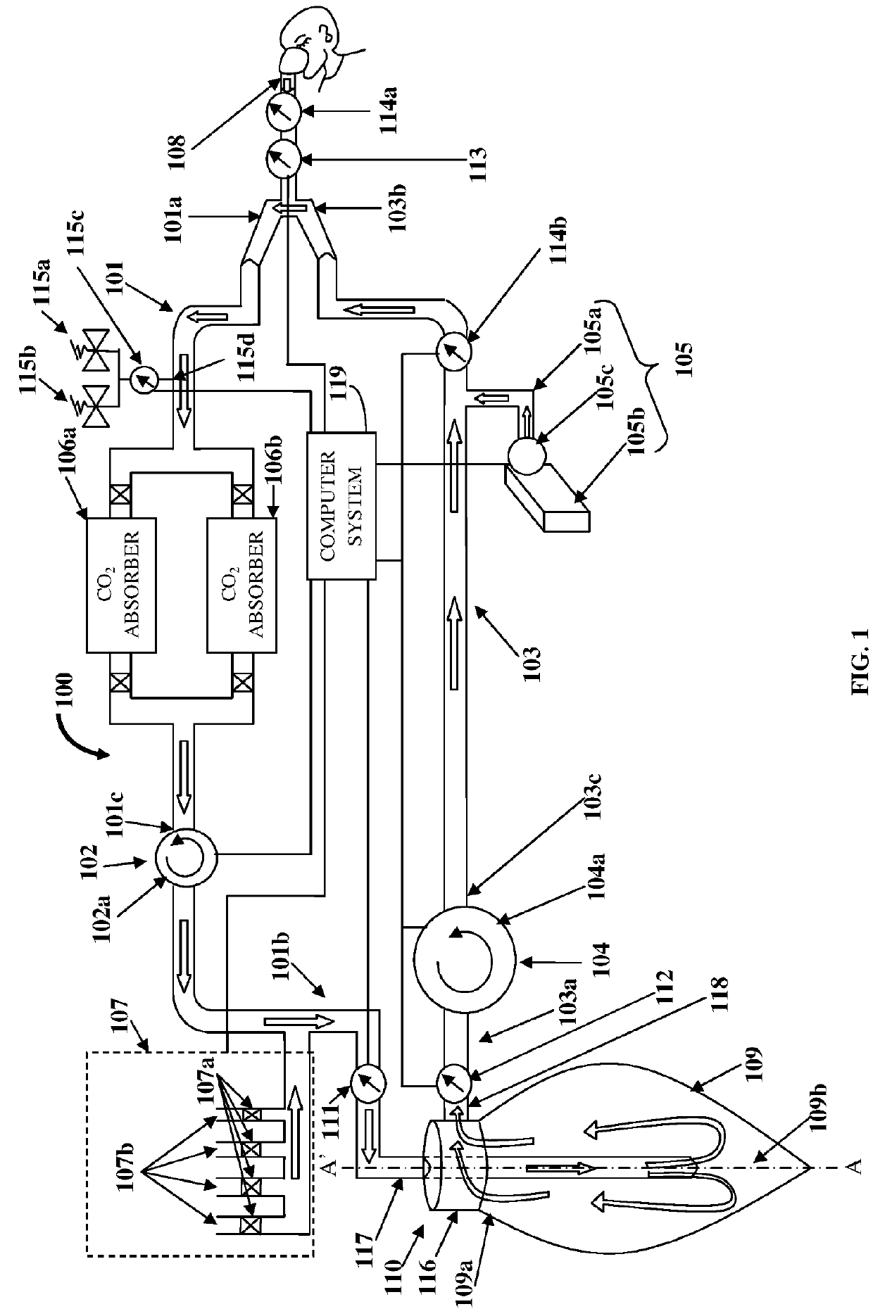
[0025]FIG. 1 illustrates an anesthesia delivery and ventilation system 100 for delivering an inhalational anesthetic agent infused in air and other gases to a patient via a circulating loop for controlling flow and concentration of inspiratory section gases for administration to the patient, and for recirculating expiratory section gases. As used herein, “circulating loop” refers to a continuous loop in the anesthesia delivery and ventilation system 100 comprising an expiratory section 101 extending from a first end 101a to a second end 101b and an inspiratory section 103 extending from a first end 103a to a second end 103b, in which the expiratory section gases and the inspiratory section gases respectively, are circulated. Also, as used herein, “inspiratory section gases” refer to gases transported along the inspiratory section 103 of the circulating loop that extends from the first end 103a of the inspiratory section 103 to the second end 103b of the inspiratory section 103. Insp...


PUM


Abstract

An anesthesia delivery and ventilation system (ADVS) includes an expiratory section, a circulation flow system (CFS), an inspiratory section, a ventilation drive system (VDS), and an anesthesia delivery system (ADS). The expiratory section receives gases from a patient and the inspiratory section and fresh gases from a fresh gas supply system. An elastic mixing reservoir receives and mixes the gases circulated by the CFS with residual gases via a connector element. The inspiratory section connects to the expiratory section at one end and to a patient connector tube at the other end. The ADS infuses an anesthetic agent into the mixed gases in the inspiratory section. The VDS delivers the mixed gases with the anesthetic agent to the patient. The VDS and the CFS are controlled and operate independently of each other to provide positive end-expiratory pressure control and ventilation control to the patient without use of a proportional valve.

Description

BACKGROUND[0001]An anesthesia circulating loop is used for delivering gases comprising oxygen and other gases optionally infused with an inhalational anesthetic agent to a patient under positive end-expiratory pressure and for providing ventilation control to the patient. Positive end-expiratory pressure is the pressure in the lungs of a patient, clinically referred to as “alveolar pressure”, at the end of expiration. As used herein, the term “ventilation” refers to a process of providing mechanical assistance to a patient for breathing. The anesthesia circulating loop comprises an expiratory section and an inspiratory section. The anesthesia circulating loop allows breathing gases to be forced into the patient to preclude apnea, which is a major effect of anesthesia. As used herein, “breathing gases” refer to gases inhaled by the patient from the anesthesia circulating loop and gases exhaled by the patient into the anesthesia circulating loop during breathing. Also, as used herein,...

Claims


Application Information

Patent Timeline
Patent Type & Authority Applications(United States)
IPC IPC(8): A61M16/08A61M16/00A61M16/12A61M16/10
CPCA61M16/0891A61M16/0875A61M16/0045A61M16/12A61M16/104A61M16/0816A61M2016/1035A61M16/0078A61M16/1005A61M2016/0036A61M2016/0027A61M2205/3368A61M16/0066A61M16/01A61M16/06A61M16/08A61M16/18A61M16/22A61M2016/0039A61M2016/0042A61M2205/3334A61M16/0069A61M16/0081A61M16/209A61M16/024A61M16/022
Inventor RAJAN, GOVINDA NALLAPPAGOMMERS, DIEDERIK ANTONIUS MARIA PAULUS JOHANNES
Owner KIRURA HLDG BV
Why Eureka
Try Eureka