Keyswitch structure

a keyswitch and structure technology, applied in the field of keyswitch structure, can solve the problems of limited dislocation space required for the keyswitch structure, difficulty in applying the keyswitch structure to thin keyboards, and the structural complexity of the supporting member, so as to improve the stability of force transfer, increase the volume of the support member, and produce the effect of feedback

Active Publication Date: 2016-11-29
DARFON ELECTRONICS CORP
View PDF6 Cites 15 Cited by
  • Summary
  • Abstract
  • Description
  • Claims
  • Application Information

AI Technical Summary

Benefits of technology

[0006]A keyswitch structure according to invention includes a bottom plate, a keycap, a first support, a second support, a magnetic member. The bottom plate has a magnetic portion. The keycap is disposed above the bottom plate. The first support is disposed between the bottom plate and the keycap. The second support is disposed between the bottom plate and the keycap. The keycap is capable of moving up and down relative to the bottom plate through the first support and the second support. The magnetic member is disposed between the bottom plate and the keycap corresponding to the magnetic portion. An attractive force is induced between the magnetic member and the magnetic portion. The magnetic member and the magnetic portion induce an attractive force therebetween. The attractive force makes the magnetic member contact and apply force to the first support and the second support so that the first support and the second support are driven to move the keycap away from the bottom plate. In practice, the first support can be a plastic part (for example a plastic injection part). The magnetic member can be directly fixed on the first support (for example by insert molding), so that the first support and the magnetic member are joined to be a single member and act together, which improves the stability of the force transfer between the magnetic member and the first support.
[0007]Compared with the prior art, the mechanism (i.e. the magnetic member and the magnetic portion), which the keyswitch structure according to the invention uses to produce a restoration force, can operate normally with not much space, so that a constraint on the structural and movement of the first support and the second support can be reduced. Furthermore, a required magnitude of the attractive force can be met by choosing proper materials for the magnetic member and the magnetic portion, without increasing the volume thereof. Thereby, the movement stability and structural strength of the first support and the second support can be maintained in a certain degree or better. Therefore, the keyswitch structure according to the invention can overcome the problem in the prior art that when the conventional keyswitch structure is applied to a thin keyboard, its keycap can hardly act stably and the feedback feeling produced thereby is insufficient.

Problems solved by technology

However, the scissors supporting member consists of cross-connected supports, in which the silicone dome is disposed, so that the supporting member has a certain degree of structural complexity.
Furthermore, the silicone dome needs a certain volume for providing a user a sufficient pressing feedback feeling (i.e. a reaction force the user feels when pressing the keycap), which leads to a limitation on the disposition space required for the keyswitch structure.
Therefore, it is difficult to apply the keyswitch structure to thin keyboards unless the movement stability of the keycap can be reduced or ignored.

Method used


Image

  • Keyswitch structure
  • Keyswitch structure
  • Keyswitch structure

Examples


Embodiment Construction

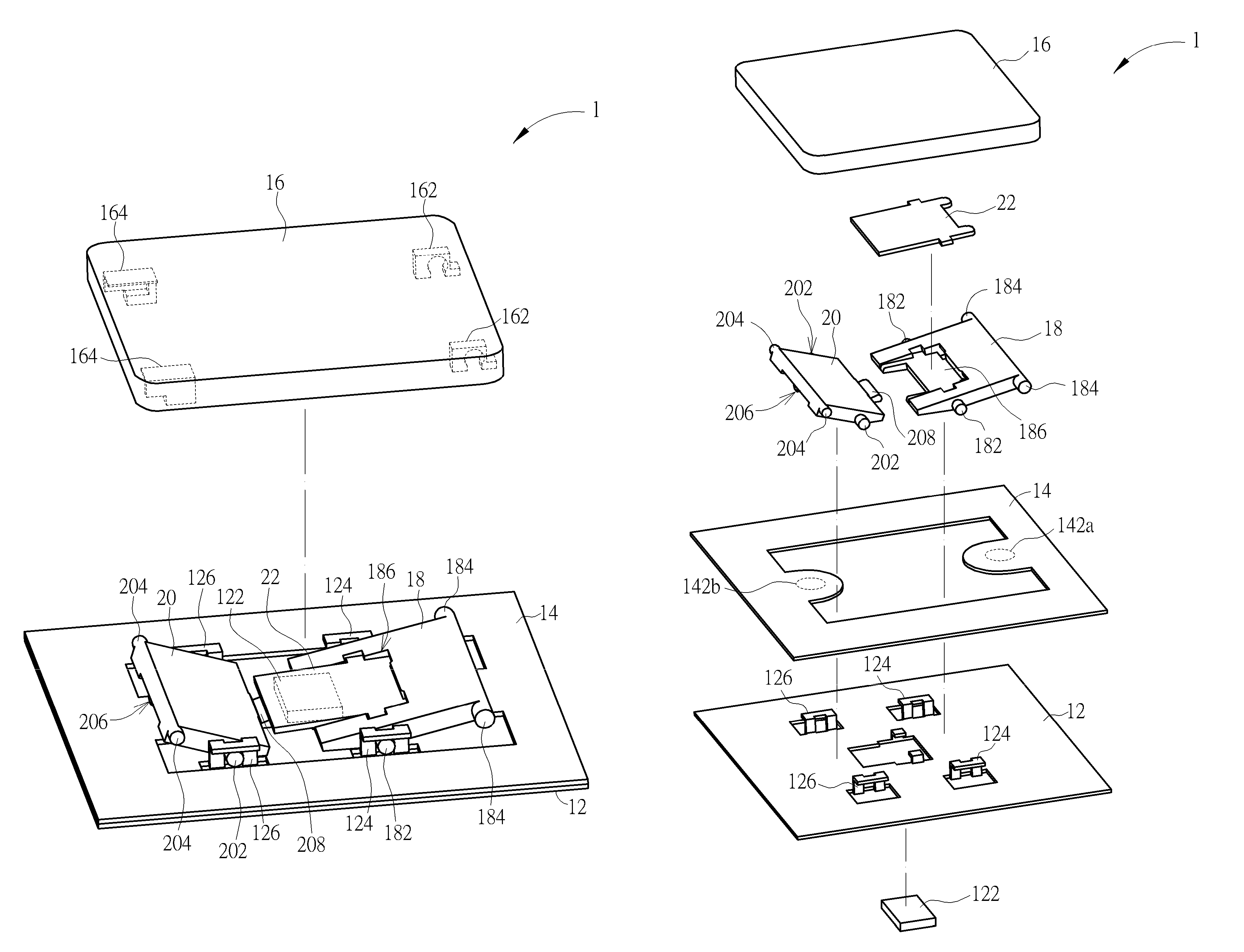
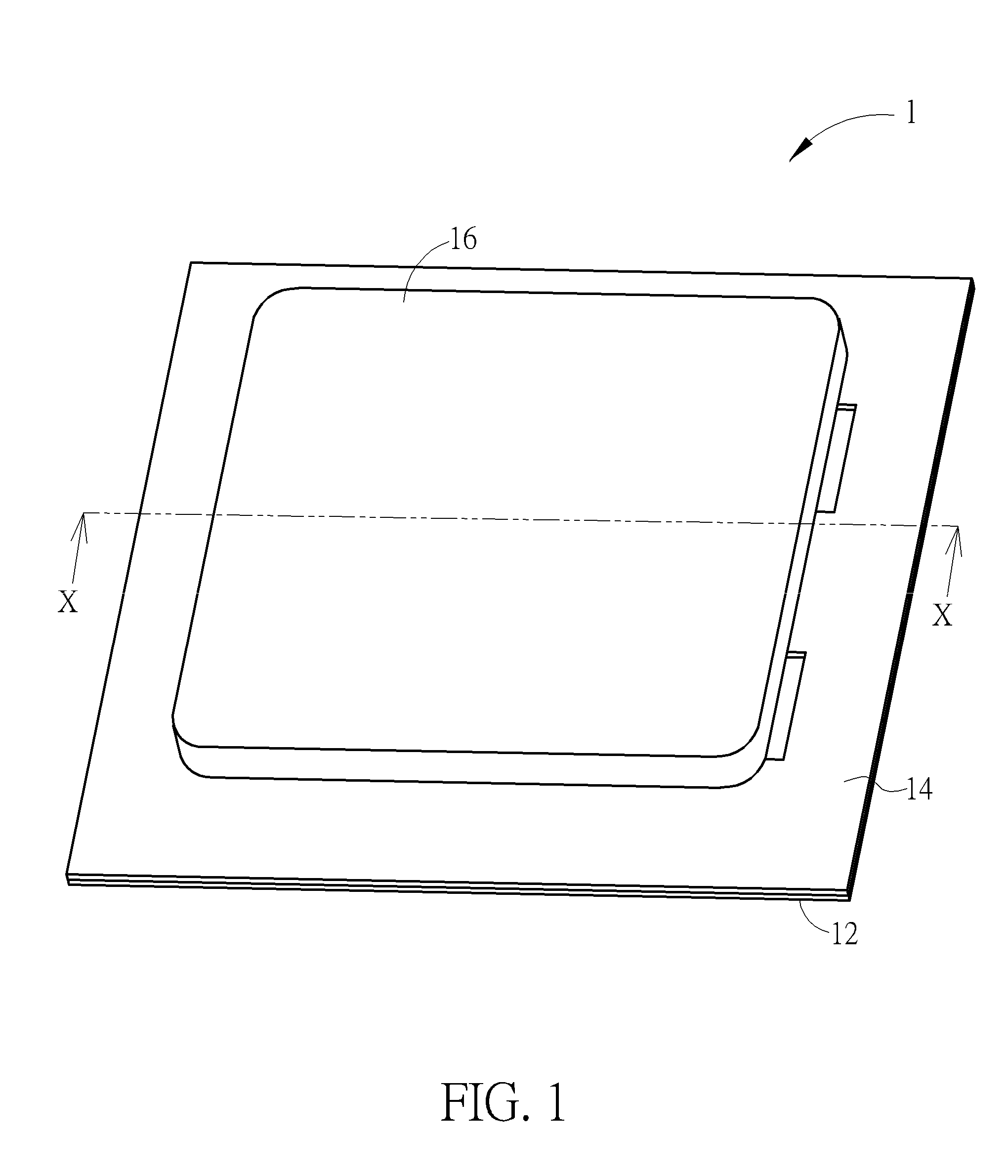
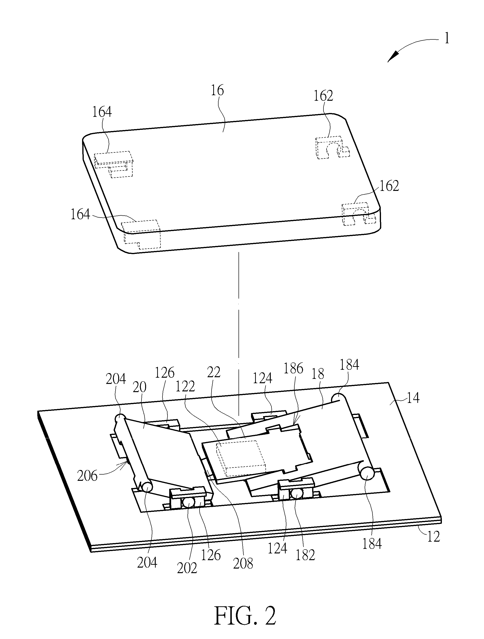
[0029]Please refer to FIGS. 1 to 4. FIG. 1 is a schematic diagram illustrating a keyswitch structure 1 of an embodiment according to the invention. FIG. 2 is a partially-exploded view of the keyswitch structure 1. FIG. 3 is an exploded view of the keyswitch structure 1. FIG. 4 is a sectional view of the keyswitch structure 1 along the line X-X in FIG. 1. The keyswitch structure 1 includes a bottom plate 12, a membrane circuit board 14, a keycap 16, a first support 18, a second support 20, and a magnetic member 22. The bottom plate 12 has a magnetic portion 122 (shown by hidden lines in FIG. 2) and a plurality of connection portions 124 and 126. In the embodiment, the bottom plate 12 mainly is a combination of a metal pressing part with a magnet (that acts as the magnetic portion 122); however, the invention is not limited thereto. The membrane circuit board 14 is stacked on the bottom plate 12 and has two switches 142a and 142b (represented by dashed circles in FIG. 3). Therein, the...


PUM


Abstract

A keyswitch structure includes a bottom plate, a keycap, a first support, a second support, and a magnetic member. The bottom plate has a magnetic portion. The keycap is disposed above the bottom plate. The first support and the second support are disposed between the bottom plate and the keycap. The keycap is capable of moving up and down relative to the bottom plate through the first support and the second support. The magnetic member is disposed between the bottom plate and the keycap corresponding to the magnetic portion. The magnetic member and the magnetic portion induce an attractive force therebetween. The attractive force makes the magnetic member contact and apply force to the first support and the second support so that the first support and the second support tend to move the keycap away from the bottom plate.

Description

BACKGROUND OF THE INVENTION[0001]1. Field of the Invention[0002]The invention relates to a keyswitch structure, and especially relates to a keyswitch structure using magnetic attractive force for restoration.[0003]2. Description of the Prior Art[0004]Conventional keyswitch structures usually have a scissors supporting member by which a keycap can move up and down. The keyswitch structure also has a resilient member (e.g. silicone dome) that is disposed under the keycap and produces a restoration force to move the keycap to its original position (i.e. where the keycap is not press). The supporting member and the resilient member are usually disposed compactly for a reduction in the disposition space required for the keyswitch structure. However, the scissors supporting member consists of cross-connected supports, in which the silicone dome is disposed, so that the supporting member has a certain degree of structural complexity. Furthermore, the silicone dome needs a certain volume fo...

Claims


Application Information

Patent Timeline
Patent Type & Authority Patents(United States)
IPC IPC(8): H01H13/7065H01H3/12
CPCH01H13/7065H01H3/125H01H2221/04H01H2231/002
Inventor HSU, CHIEN-SHIH
Owner DARFON ELECTRONICS CORP
Why Eureka
Try Eureka