Check patentability & draft patents in minutes with Patsnap Eureka AI!

Driving force control apparatus for a four-wheel drive vehicle

a four-wheel drive vehicle and driving force control technology, applied in mechanical devices, electric devices, transportation and packaging, etc., can solve the problems of not being able the energy consumed by the tire treads of the respective wheels, and the inability to reduce the energy consumed, so as to achieve the effect of reducing the energy consumed

Active Publication Date: 2016-12-27
TOYOTA JIDOSHA KK
View PDF9 Cites 0 Cited by
  • Summary
  • Abstract
  • Description
  • Claims
  • Application Information

AI Technical Summary

Benefits of technology

This approach minimizes the sum of energy consumed by tire treads across all wheels, regardless of the magnitude and direction of tire sliding vectors, even during turns, acceleration, or deceleration, thereby extending the vehicle's cruising distance per battery charge.

Problems solved by technology

Respective drive wheels are in contact with a road surface through tires, and the driving force is transmitted to the road surface via the tires, with the result that energy is consumed by the tire treads of the respective wheels.
Thus, it is only possible to reduce the energy that is consumed due to a lateral slide of the tires of respective drive wheels on the treads caused when the vehicle makes a turn at a constant vehicle speed.
In other words, it is not possible to reduce energy that is consumed due to a longitudinal slide of the tires of respective drive wheels on the treads caused as in the case of the vehicle making a turn with acceleration or deceleration.
Thus, in the four-wheel drive vehicle in which driving forces are applied to the front left and right wheels and the rear left and right wheels, it is not possible to optimally control the driving forces of the four wheels so as to reduce energy consumed when the tires of respective drive wheels slide on the treads.

Method used


Image

  • Driving force control apparatus for a four-wheel drive vehicle
  • Driving force control apparatus for a four-wheel drive vehicle
  • Driving force control apparatus for a four-wheel drive vehicle

Examples


Embodiment Construction

[0022]Now, a preferred embodiment of the present invention is described in detail with reference to the accompanying drawings.

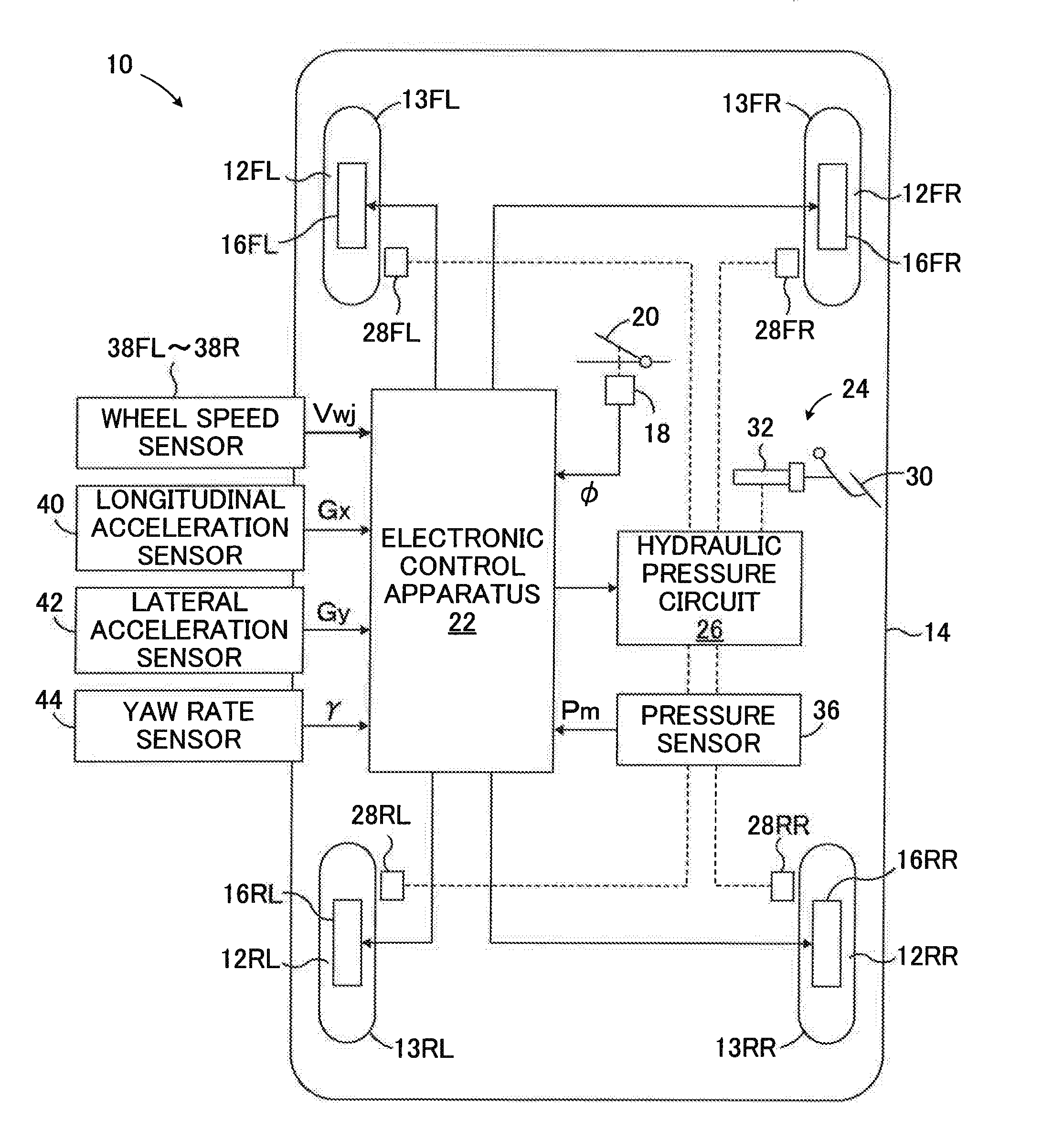
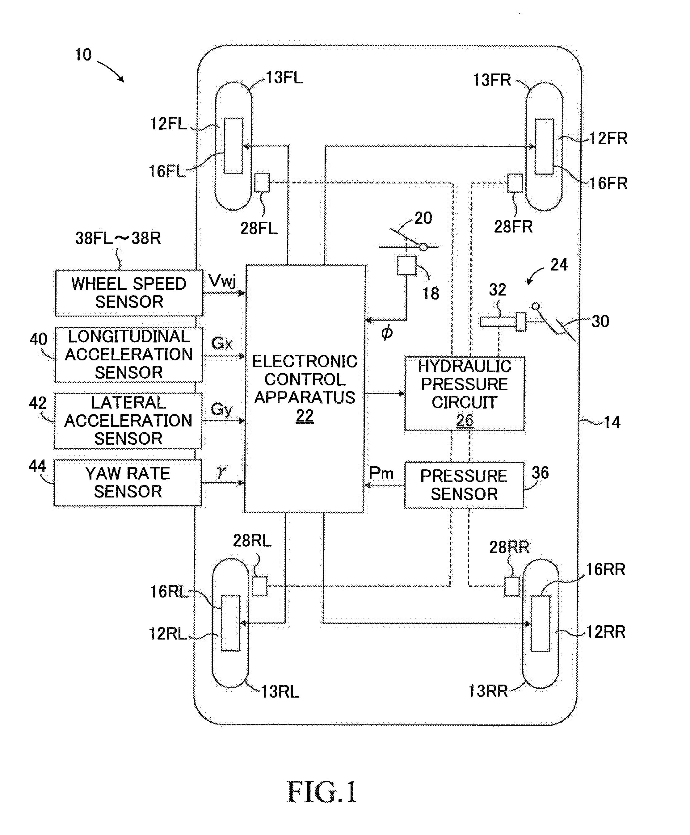
[0023]FIG. 1 is a schematic configuration diagram for illustrating a driving force control apparatus 10 for a vehicle applied to a four-wheel drive vehicle having in-wheel motors according to an embodiment of the present invention.

[0024]As illustrated in FIG. 1, the driving force control apparatus 10 is applied to a vehicle 14 having front left and right wheels 12FL and 12FR, which are steered wheels, and rear left and right wheels 12RL and 12RR, which are unsteered wheels. Although not illustrated in detail in FIG. 1, the front wheels 12FL and 12FR have tires 13FL and 13FR, which are mounted to metal wheels, respectively, and the rear wheels 12RL and 12RR have tires 13RL and 13RR, which are mounted to metal wheels, respectively.

[0025]The front wheels 12FL and 12FR are driven by being applied with driving forces independently of each other by in-wheel motors ...


PUM


Abstract

Provided is a driving force control apparatus (10) configured to control driving forces applied to four wheels by controlling a driving force application apparatus (in-wheel motors (16FL to 16RR) and friction braking apparatus (24)) configured to apply driving forces to front left and right wheels (12FL and 12FR) and rear left and right wheels (12RL and 12RR) independently. The driving force control apparatus (10) is configured to: calculate vehicle body speeds Vj at positions of the four wheels, vertical loads Fzj of the four wheels, and a driving force Fx required by a driver (S30 to S50); calculate, based on those values, target driving forces Fxj for the four wheels to set tire sliding vectors of the four wheels to be the same (S60); and control the driving force application apparatus such that the driving forces of the four wheels are equal to corresponding target driving forces, respectively (S70).

Description

BACKGROUND OF THE INVENTION[0001]1. Field of the Invention[0002]The present invention relates to a driving force control apparatus configured to control driving forces to be applied to front left and right wheels and rear left and right wheels of a four-wheel drive vehicle.[0003]2. Description of the Related Art[0004]In an electric vehicle such as an electric automobile, left and right drive wheels are driven by respective electric motors or a common electric motor. The driving forces of the left and right drive wheels are controlled, so as to that the sum of those driving forces is equal to a driving force required by a driver, to take the same value, or to take values different from one another by optionally, independently controlling outputs of respective electric motors.[0005]Respective drive wheels are in contact with a road surface through tires, and the driving force is transmitted to the road surface via the tires, with the result that energy is consumed by the tire treads o...

Claims


Application Information

Patent Timeline
Patent Type & Authority Patents(United States)
IPC IPC(8): B60W10/04B60W10/119B60W30/18
CPCB60W30/18B60W10/04B60L15/20B60L15/2009B60L2240/461B60L2240/12B60L2240/16B60L2240/18B60L2240/423B60L2260/28B60W10/08B60W10/184B60W10/188B60W30/02B60W30/188B60W2520/10B60W2520/105B60W2520/125B60W2520/14B60W2520/28B60W2540/10B60W2540/12B60W2710/083B60W2710/182B60W2720/20B60W2720/403B60W2720/406B60Y2200/91Y02T10/84B60L2240/24B60L15/2036B60L2220/46B60L2240/22B60L2250/26Y02T10/72B60L2240/26Y02T10/40Y02T10/64B60L15/34
Inventor KATSUYAMA, ETSUOKOBAYASHI, TAKAOSUGIURA, HIDEKI
Owner TOYOTA JIDOSHA KK
Features
  • R&D
  • Intellectual Property
  • Life Sciences
  • Materials
  • Tech Scout
  • Unparalleled Data Quality
  • Higher Quality Content
  • 60% Fewer Hallucinations
Learn More