Method and apparatus for machining a workpiece by way of a geometrically defined blade

a geometrically defined blade and workpiece technology, applied in driving apparatus, maintenance and safety accessories, railway tracks, etc., can solve the problems of unnecessary remachining operation, for example grinding operation, and achieve the effect of less wear, less concentricity error, and no time-consuming tool chang

Active Publication Date: 2016-12-27
SCHWEERBAU INT GMBH & CO KG
View PDF63 Cites 0 Cited by
  • Summary
  • Abstract
  • Description
  • Claims
  • Application Information

AI Technical Summary

Benefits of technology

[0011]There is thus provided, according to the invention, a method for the stock-removing machining of a workpiece, wherein the cutter is moved along a straight path during the stock-removing machining of the workpiece. This makes it possible for the surface of the workpiece to be remachined at a high advance speed without the occurrence of undulations. In this case, the advantages of planing are combined with the advantages of milling. The cutter, which revolves as in the case of milling, can be moved at a high speed relative to the workpiece. The rectilinear motion of the cutter during the stock-removing machining results in a machining of the workpiece that resembles planing. In this combination, a high advance speed can be achieved, with a small force requirement and a high removal rate, in one operation, the surface of the machined workpiece being planar and without undulations. With this rotary planing method, a remachining operation, for example a grinding operation, is unnecessary. The uninterrupted rotary planing allows face machining of a workpiece of theoretically endless length and of any cross-sectional geometry.
[0026]It is advantageous that the cutters disposed next to one another and / or in series are realized according to the cross-sectional geometry of the workpiece. This enables a workpiece having a complex cross-sectional geometry to be machined by means of the apparatus. Geometrically defined cutters allow machining of differing cross-sectional geometries such as straight lines, curves and / or polygons. Owing to the fact that the magnitude of the deflection of the individual cutters can be set, it is possible to vary the cross-sectional geometry of the workpiece during the machining operation. It thereby becomes possible to influence also the geometry of the workpiece in its longitudinal axis.

Problems solved by technology

With this rotary planing method, a remachining operation, for example a grinding operation, is unnecessary.

Method used


Image

  • Method and apparatus for machining a workpiece by way of a geometrically defined blade
  • Method and apparatus for machining a workpiece by way of a geometrically defined blade
  • Method and apparatus for machining a workpiece by way of a geometrically defined blade

Examples


Embodiment Construction

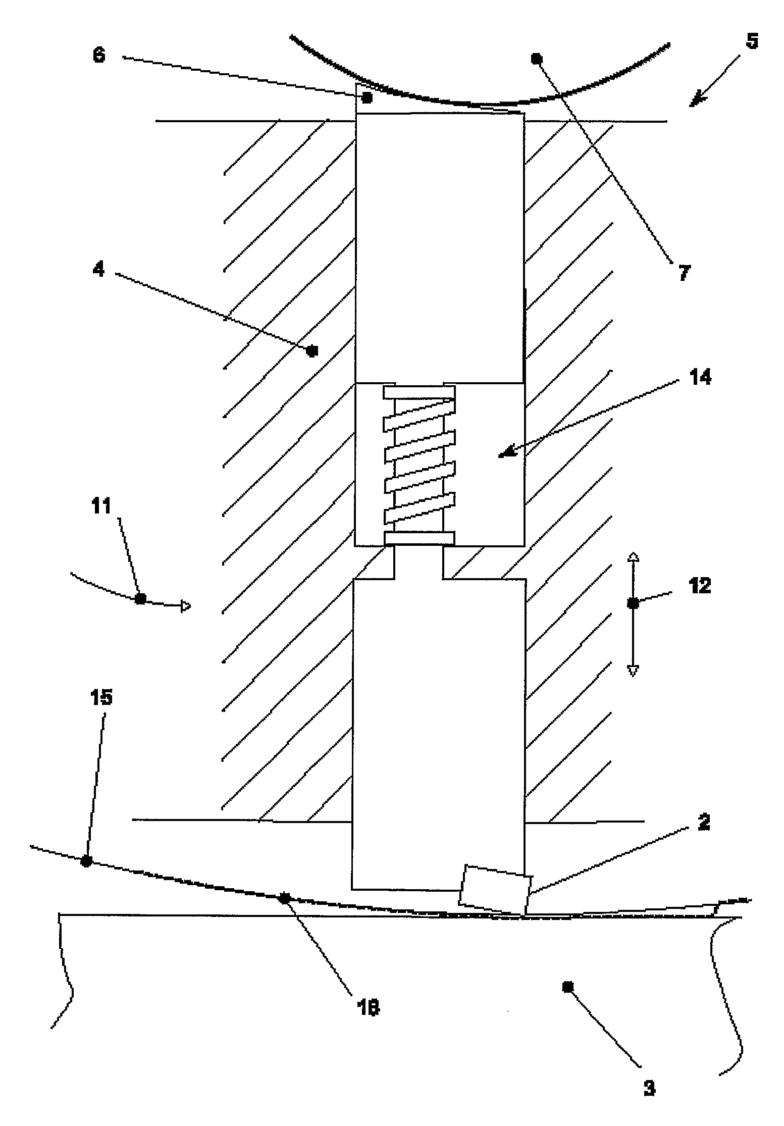
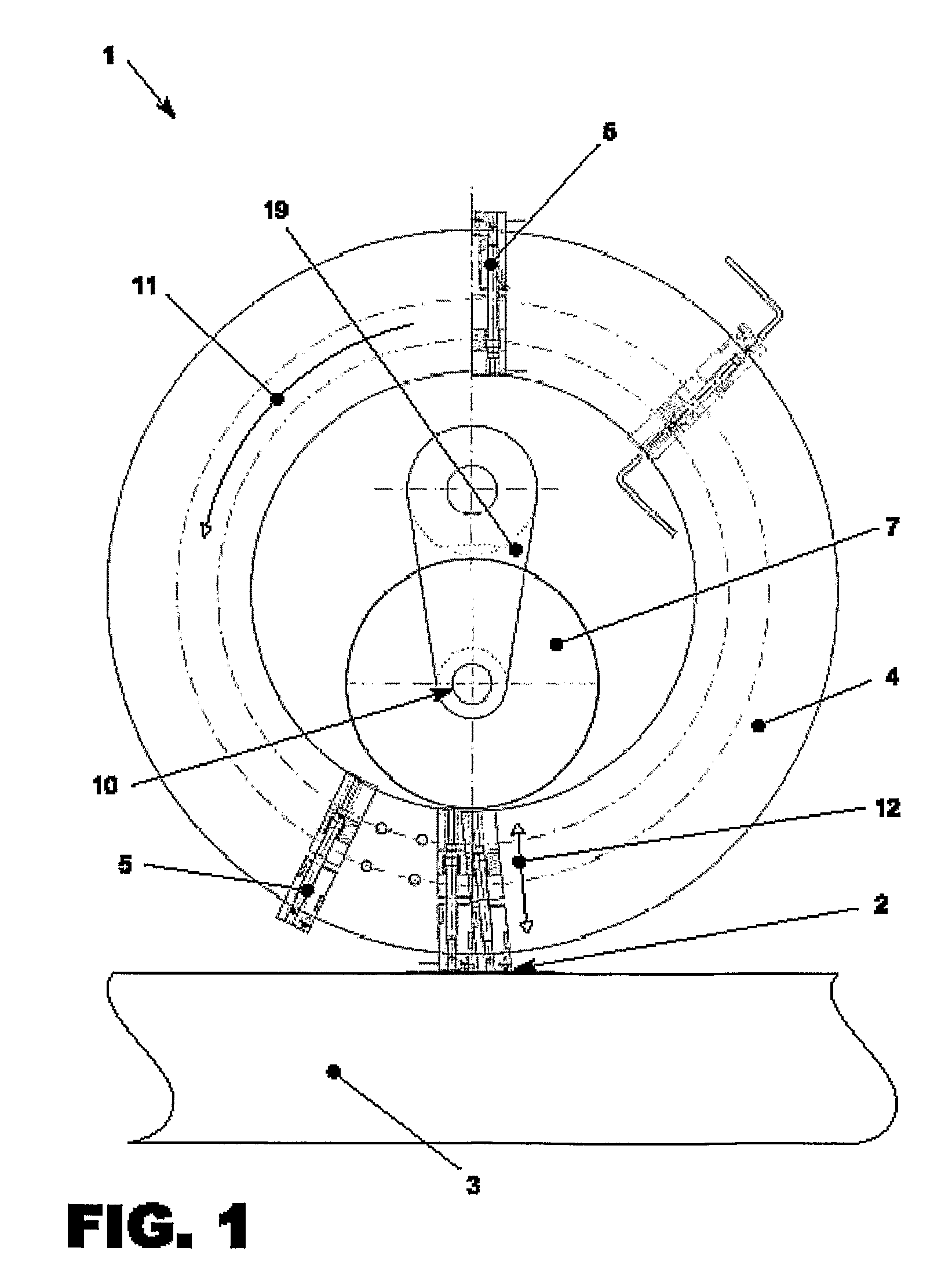
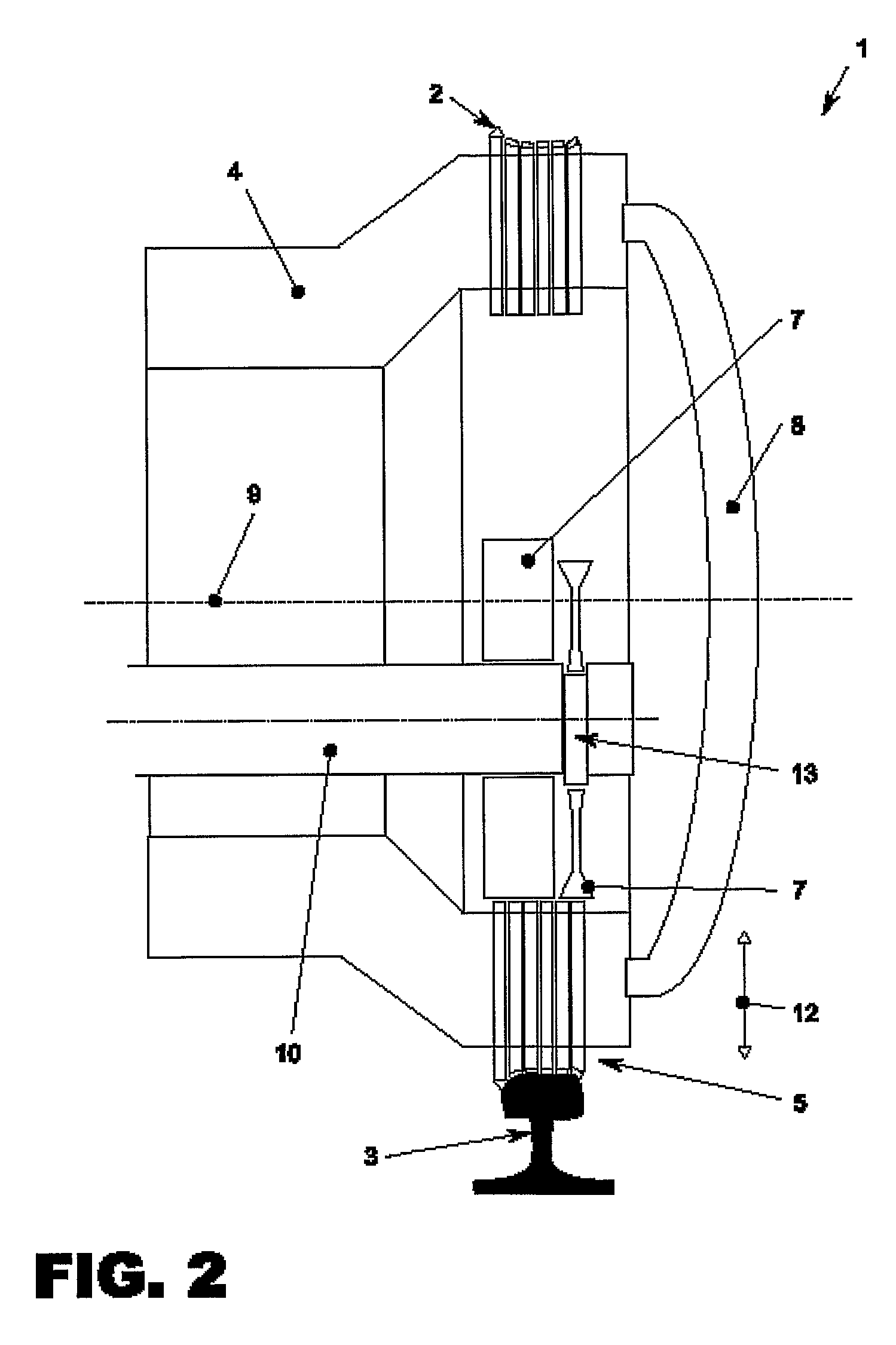
[0032]FIGS. 1 to 3 show an apparatus 1 having a geometrically defined cutter 2 for the stock-removing machining of a workpiece 3. The workpiece 3 represented in section in this drawing is a rail of a track body. The apparatus 1 serves to machine the workpiece 3. In the case of a rail, after a certain period of operation and / or if wear occurs, it is necessary to rework, i.e. to smooth, the surface, to machine off running-surface material, in order to remove hairline cracks and / or restore the cross-sectional geometry. Particular attention in this case is paid to the creation of a surface that is as smooth as possible, in particular in the region of the wheel run. The machining of the workpiece 3 is effected by means of a cutter 2, which, by means of a receiver 5, is disposed on a carrier 4 that can be driven revolvingly about the axis 9. A casing 8 prevents dirt and foreign bodies from entering the apparatus 1 and damaging the latter. To enable servicing work to be performed speedily,...


PUM

PropertyMeasurementUnit
distanceaaaaaaaaaa
depthaaaaaaaaaa
mechanical stressaaaaaaaaaa

Abstract

A method for stock-removal machining of a surface of a workpiece includes driving a carrier revolvingly about an axis so as to move at least one geometrically defined cutter disposed on the carrier via a receiver on a revolution path about the axis; and moving the cutter relative to the carrier during the machining, so that the cutter moves in a straight path relative to the surface of the workpiece.

Description

CROSS REFERENCE TO PRIOR APPLICATIONS[0001]This application is a U.S. National Phase Application under 35 U.S.C. §371 of International Application No. PCT / DE2009 / 001417, filed on Oct. 13, 2009, and claiming priority to European Application No. EP 08 018 311.4, filed on Oct. 20, 2008. The International Application was published in German on Apr. 29, 2010 as WO 2010 / 045919 under PCT Article 21 (2).FIELD[0002]The invention relates to a method for the stock-removing machining of a workpiece, in particular rails of a track body, wherein at least one geometrically defined cutter is moved on a revolution path about an axis. The invention furthermore relates to an apparatus having a geometrically defined cutter for the stock-removing machining of a workpiece, in particular rails of a track body, which apparatus has a revolvingly drivable carrier on which the cutter is disposed by means of a receiver.BACKGROUND[0003]A workpiece within the meaning of the invention is a body to be machined, ha...

Claims


Application Information

Patent Timeline
Patent Type & Authority Patents(United States)
IPC IPC(8): B23D13/04E01B31/13B23D13/00
CPCE01B31/13B23D13/04B23D13/00Y10T409/303752Y10T409/309184Y10T409/509676
Inventor MEVERT, FRANKSANDER, KURT
Owner SCHWEERBAU INT GMBH & CO KG
Why Eureka
Try Eureka