Multi-rotor aircraft

A multi-rotor aircraft and rotor technology, applied in the field of aircraft, can solve the problems of low lift and weight, poor stability and maneuverability, and low forward flight speed of the aircraft, so as to improve the carrying capacity, increase the lift/weight ratio, and eliminate the reaction Effect of Torque Difference

Inactive Publication Date: 2012-12-05
CHANGCHUN INST OF OPTICS FINE MECHANICS & PHYSICS CHINESE ACAD OF SCI
View PDF4 Cites 12 Cited by
  • Summary
  • Abstract
  • Description
  • Claims
  • Application Information

AI Technical Summary

Problems solved by technology

The common problems of the above-mentioned rotorcraft are: it is a kinematic coupling system itself, the direction and attitude in flight are coupled, the stability and maneuverability are poor, the forward flight speed is low, the lift and weight of the aircraft are relatively low, and the design Poor carrying capacity when it becomes a small aircraft

Method used


Image

  • Multi-rotor aircraft
  • Multi-rotor aircraft
  • Multi-rotor aircraft

Examples


Embodiment 1

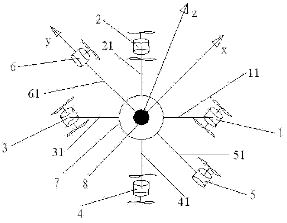
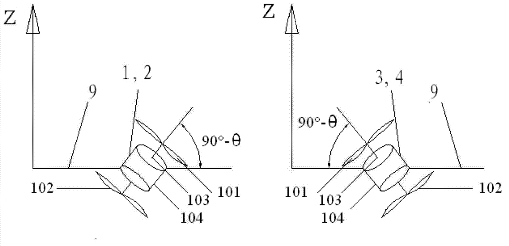
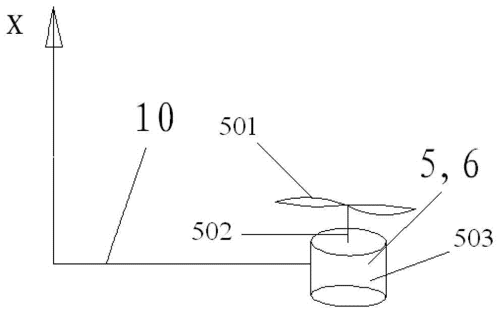
[0038] Such as figure 1Shown, the present invention comprises four main rotor systems 1,2,3,4, two auxiliary rotor systems 5,6, body 7, and the integrated flight system 8 that is installed in body 7, and body 7 peripheral stretches out six Connecting rods 11, 21, 31, 41, 51, 61, flight integrated system 8 includes control system, inertial sensor and attitude measurement system, navigation system, image acquisition and transmission system, the origin of the body coordinate system of the aircraft is the center of gravity of the aircraft , the z-axis is vertically upward, the x-axis is perpendicular to the z-axis and points forward, the y-axis is determined by the right-hand rule, the auxiliary rotor systems 5 and 6 are distributed on both sides of the x-axis, and the main rotor systems 1~4 are respectively distributed in the body coordinate system within the four quadrants of the xy plane. The four main rotor systems 1, 2, 3, and 4 are equipped with coaxial reversed double roto...

Embodiment 2

[0043] Such as Figure 5 As shown, the main rotor system 111 comprising four ducted propeller structures, the auxiliary rotor system 511 of two ducted propeller structures, the dish-shaped body 711, and the flight integrated system 811 installed in the body 711, the flight integrated system 811 includes Control system, inertial sensor and attitude measurement system, navigation system, image acquisition and transmission system, the origin of the body coordinate system of the aircraft is the center of gravity of the aircraft, the z-axis is vertically upward, the x-axis is perpendicular to the z-axis, pointing forward, and the y-axis Determined by the right-hand rule, the auxiliary rotor system 511 is distributed on both sides of the x-axis, and the four main rotor systems 111 are respectively distributed in four quadrants of the xy plane of the body coordinate system. Among the four main rotor systems, each rotation axis of main rotor systems 1 and 2 forms a clockwise 45° angle...


PUM


Abstract

The invention relates to a multi-rotor aircraft, which comprises four main rotor systems, two auxiliary rotor systems, a body and a flying integrated system arranged in the body, wherein an original point of a coordinate system of the body is the gravity center of the aircraft; a z axis is vertical upwards; an x axis is vertical to the z axis and points to the front part; a y axis is determined by a right-hand rule; the four main rotor systems are respectively distributed inside four quadrants of an x-y plane of the body coordinate system; each rotary axis of the four main rotor systems and the z axis of the body coordinate system form an included angle theta, and a projection of each rotary axis on an x-o-y plane of the body coordinate system is overlapped with the projection of a connection line from a rotation center to the original point of the body coordinate system on the x-o-y plane of the body coordinate system. According to the invention, movement and gesture change of the aircraft can be achieved by adjusting rotating speed of the four main rotor systems and the two auxiliary rotor systems; and the aircraft can achieve the actions such as vertical take-off and landing, forward flying, reverse flying, hovering, rolling and the like, and the stability and the controllabitity are good.

Description

technical field [0001] The invention relates to the field of aircraft, in particular to a multi-rotor aircraft. Background technique [0002] Rotor-type aircraft with functions such as vertical take-off and landing and hovering not only play an important role in the military field, but also show great application potential in disaster scene rescue, dangerous environment detection, traffic surveillance or aerial photography, and have been widely accepted. focus on. [0003] At present, rotorcraft mainly include four structural forms: single-rotor (main rotor + tail rotor) helicopter, double-rotor (coaxial reverse propeller) helicopter, quad-rotor aircraft and six-rotor aircraft, such as the MH-16 helicopter of McDonnell Douglas , Russia's Ka-29 helicopter, Germany's Microdrone company, Canada's Dranganflyer company's quadrotor aircraft, etc. Single-rotor helicopters or coaxial reverse-rotor helicopters need tail rotors to eliminate the torsion produced by the rotors on the ...

Claims


Application Information

Patent Timeline
Patent Type & Authority Applications(China)
IPC IPC(8): B64C27/02B64C27/32
Inventor 高庆嘉白越孙强
Owner CHANGCHUN INST OF OPTICS FINE MECHANICS & PHYSICS CHINESE ACAD OF SCI
Why Eureka
Try Eureka