Switching assembly and interconnect assembly therefor

a technology of interconnection assembly and switch assembly, which is applied in the direction of relays, coupling device connections, electrical apparatus contruction details, etc., can solve the problems of galvanic corrosion, reduced clamping force, and easy damage of threads in ridged bus bars

Active Publication Date: 2016-12-27
LABINAL
View PDF13 Cites 8 Cited by
  • Summary
  • Abstract
  • Description
  • Claims
  • Application Information

AI Technical Summary

Problems solved by technology

A known problem with the aforementioned method of mounting is that threads in the ridged bus bars become easily damaged.
Additionally, once the bolts are threaded, plating is removed from the bolts, which leads to galvanic corrosion.
Also, aluminum bus bars have large coefficients of thermal expansion which may cause clamp forces to decrease over time, creating a relatively high resistance connection that leads to overheating.
Finally, such threaded connections require labor to install, remove and / or repair.

Method used


Image

  • Switching assembly and interconnect assembly therefor
  • Switching assembly and interconnect assembly therefor
  • Switching assembly and interconnect assembly therefor

Examples


Embodiment Construction

[0019]As employed herein, the term “number” shall mean one or an integer greater than one (i.e., a plurality).

[0020]As employed herein, the statement that two or more parts are “coupled” together shall mean that the parts are joined together either directly or joined through one or more intermediate parts.

[0021]As employed herein, the statement that two or more parts or components “engage” one another shall mean that the parts touch and / or exert a force against one another either directly or through one or more intermediate parts or component.

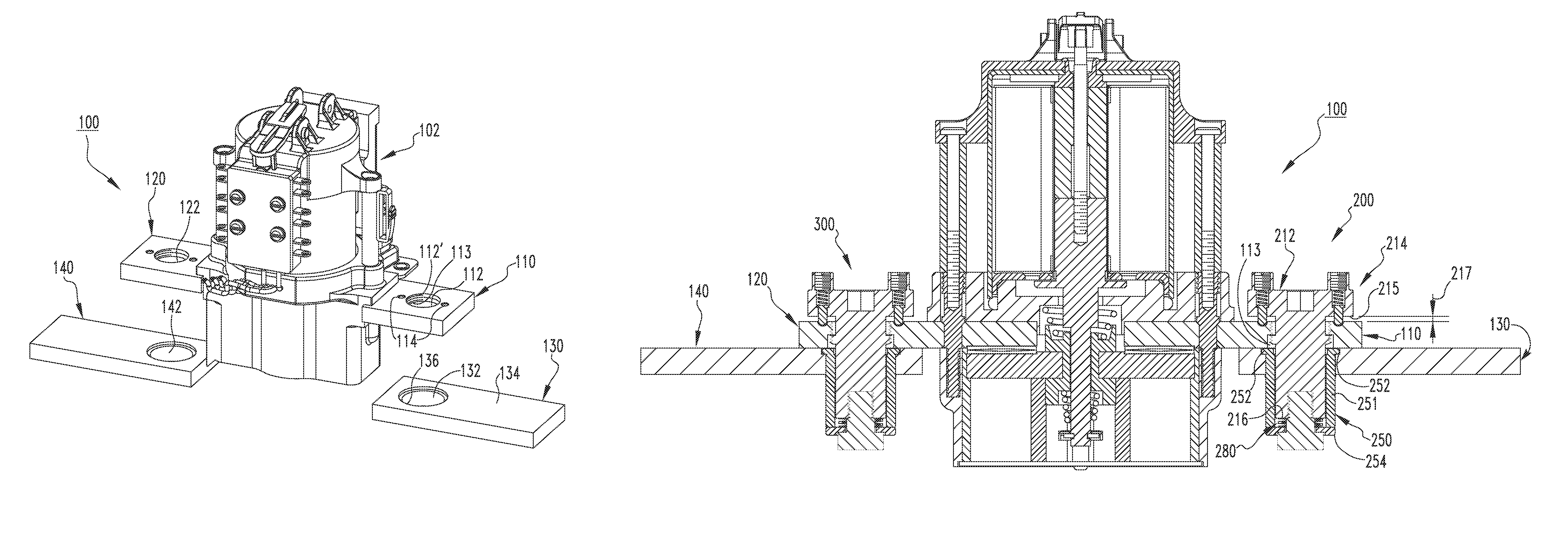
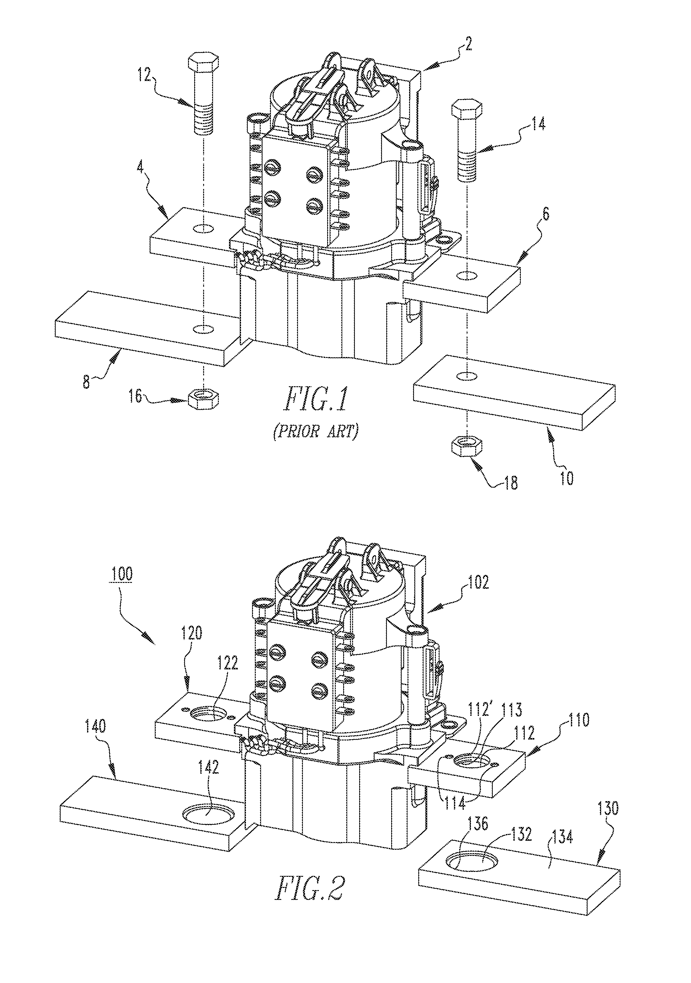
[0022]FIG. 2 shows a portion of a switching assembly 100 that includes an electromagnetic switching device (e.g., without limitation, single-phase power switching contactor 102). The power switching contactor 102 includes a pair of contactor buses 110,120 that are structured to be electrically connected and mechanically coupled to a corresponding pair of bus bars 130,140. As seen, the contactor buses 110,120 each have a corresponding through ho...


PUM


Abstract

An interconnect assembly for a switching assembly in which the switching assembly includes a bus bar and an electromagnetic switching device having a contactor bus. The interconnect assembly is structured to mechanically couple and electrically connect the contactor bus to the bus bar. The interconnect assembly includes a socket member structured to engage the bus bar, a post assembly that includes a post member structured to extend through the contactor bus, in which at least a portion of the post member extends into the socket member, and a locking member disposed on the post member. The locking member is structured to extend through and removably engage the socket member in order to mechanically couple and electrically connect the contactor bus to the bus bar.

Description

BACKGROUND[0001]Field[0002]The disclosed concept pertains generally to switching assemblies and, more particularly, to switching assemblies including electromagnetic switching devices such as for example, power switching contactors. The disclosed concept also pertains to interconnect assemblies for switching assemblies.[0003]Background Information[0004]Electromagnetic switching devices, such as for example power switching contactors, are often used to electrically couple a power source to a load such as an electrical motor or other suitable load. Known power switching contactors are commonly mounted to ridged bus bars when current is increased above 150 amperes.[0005]FIG. 1 shows a known power switching contactor 2 that includes a pair of contactor buses 4,6. As seen, the contactor buses 4,6 are structured to be mounted to a corresponding pair of bus bars 8,10. Such mounting is traditionally done by bolting the contactor buses 4,6 to the bus bars 8,10 with conventional thread bolts ...

Claims


Application Information

Patent Timeline
Patent Type & Authority Patents(United States)
IPC IPC(8): H05K7/00H05K7/12H01R3/00
CPCH05K7/12H01R3/00H01H45/04H01H50/047H01H50/14H01R25/161
Inventor MILLS, PATRICK WELLINGTONMCCORMICK, JAMES MICHAELMUCKEFUSE, JEFFREY ALAN
Owner LABINAL
Why Eureka
Try Eureka