
Industrial field real-time working condition radio alarm system

a radio alarm system and real-time working technology, applied in alarms, electric signalling details, instruments, etc., can solve the problems of affecting the evacuation as well as the life and safety of workers, and workers who are far away from the position might not be able to evacua

Active Publication Date: 2017-01-03
HARBIN EAST ALARM EQUIP DEV
View PDF14 Cites 13 Cited by
  • Summary
  • Abstract
  • Description
  • Claims
  • Application Information

AI Technical Summary

Benefits of technology

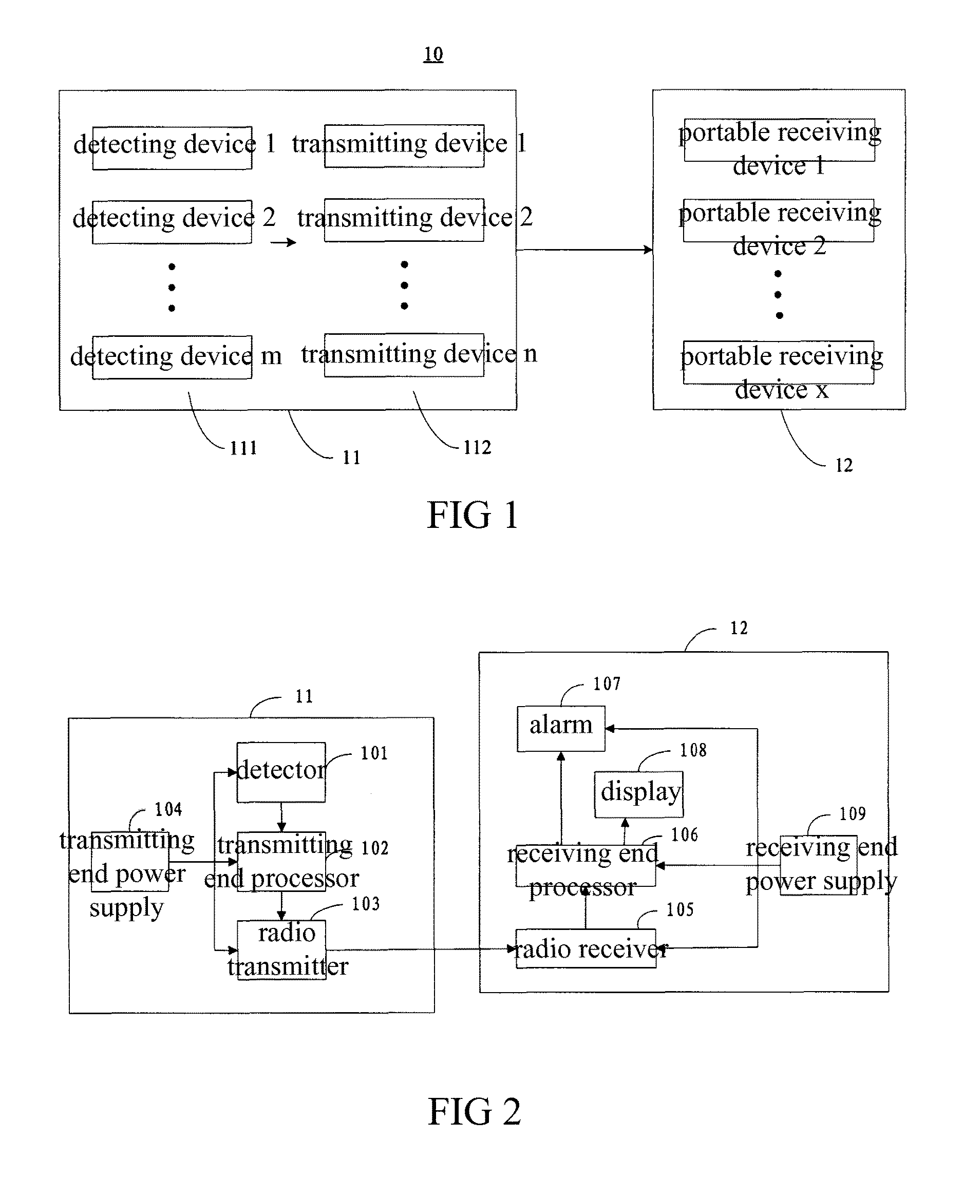
[0005]According to one aspect of the invention, the invention provides an industrial field real-time working condition radio alarm system, the system comprises a transmitting end and a receiving end carried by workers; said transmitting end comprises: a detector to detect the current working condition, a transmitting end processor to process an on-off signal sent by said detector, and a radio transmitter to transmit an alarm signal to said receiving end under the control of said transmitting end processor; said receiving end comprises: a radio receiver to receive said alarm signal, a receiving end processor to process said alarm signal sent by said radio receiver, and an alarm to send an alarm signal under the control of said receiving end processor; said transmitting end processor is connected to said detector and said radio transmitter respectively; and said receiving end processor is connected to said radio receiver and said alarm respectively.

Problems solved by technology

If the control centre failures or the reaction speed is too slow, it will badly affect the evacuation as well as the life and safety of workers.
In addition, bells, warning lamps and other devices used to indicate alarm from control centre are usually disposed at a specific position in the plants, the workers who are closer to the position may quickly alerted to evacuate in time, but the worker who far away from the position might not be able to evacuate because of not receiving the alarm in time.

Method used


Image

  • Industrial field real-time working condition radio alarm system
  • Industrial field real-time working condition radio alarm system
  • Industrial field real-time working condition radio alarm system

Examples


Embodiment Construction

[0015]The principles and characteristics of present invention will now be described, with reference to the accompanying drawings. The embodiments are only to explain the invention, but not to limit the scope of the invention.

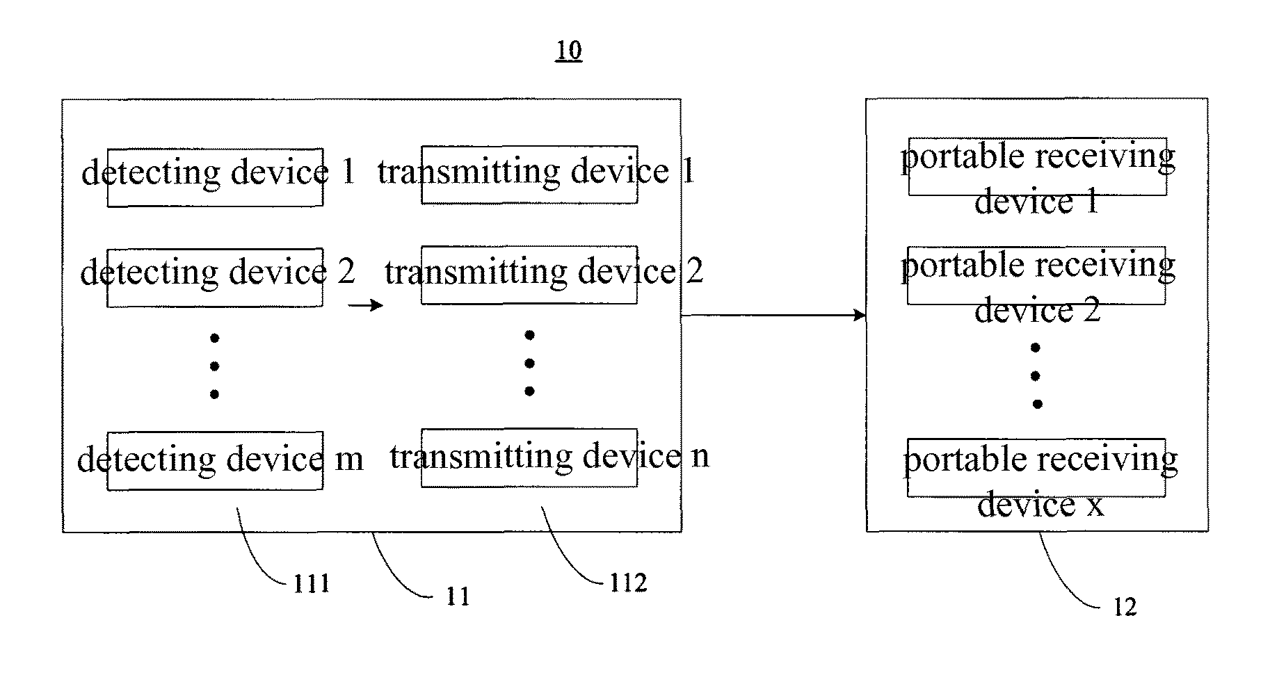
[0016]FIG. 1 shows the schematic diagram of the real-time alarm system 10 according to an embodiment of the invention. In FIG. 1, the detecting devices 1, . . . , m (m>1) detect whether the current working condition is abnormal or not, and when abnormal working condition occurs, relevant signals are generated. The transmitting devices 1, . . . , n (n>1) transmit the relevant signals generated by the detecting devices 1, . . . , m. The portable receiving devices 1, . . . , x (x>1) receive the relevant signal sent by the transmitting devices 1, . . . , n to send an alarm signal.

[0017]According to one embodiment of the invention, transmitting devices 1, . . . , n may transmit the relevant signal in a variety of suitable wireless way, and the portable receiving devi...


PUM


Abstract

An industrial field real-time working condition radio alarm system, comprises a transmitting end (11) and a receiving end (12) carried a worker; the transmitting end (11) comprises a detector (101) to detect the current working condition, a transmitting end processor (102) to process an on-off signal sent by the detector (101), and a radio transmitter (103) to transmit an alarm signal to the receiving end (12) under the control of the transmitting end processor (102); the receiving end (12) comprises a radio receiver (105) to receive the alarm signal, a receiving end processor (106) to process the alarm signal sent by the radio receiver (105), and an alarm (107) to send an alarm under the control of the receiving end processor (106); the transmitting end processor (102) is connected to the detector (101) and the radio transmitter (103) respectively; and the receiving end processor (106) is connected to the radio receiver (105) and the alarm (107) respectively. The radio alarm system can send a dangerous working condition alarm to all workers in real time.

Description

FIELD OF INVENTION[0001]The invention relates to industrial field real-time working condition alarm technology, in particularly, to an industrial field real-time working condition radio alarm system.BACKGROUND OF THE INVENTION[0002]Usually, plants and mines which dangers might occur in operation will be equipped with certain amounts of real-time working condition alarm systems, in order to detect dangerous conditions and alarm in time, thus to guarantee the life and safety of workers.[0003]In prior art, fixed or handheld detectors are assumed to detect dangerous conditions (such as dangerous gas, high pressure environment, high temperature environment etc.), when danger occurs, the detector will sent an alarm signal to a remote control centre, then the control centre will send an alarm, for example, the control centre may warning workers through ringing bells, initiating warning lamps and other means, thus the workers may evacuate in time.[0004]It can seen that, in the prior art rea...

Claims


Application Information

Patent Timeline
Patent Type & Authority Patents(United States)
IPC IPC(8): G08B1/08G08B25/10G08B25/01G08B27/00G08B21/12
CPCG08B25/10G08B25/016G08B27/008G08B21/12
Inventor MAO, FEIWANG, WEIGANGLI, XUANNANLIU, JILONG
Owner HARBIN EAST ALARM EQUIP DEV
Learn More