Pulse measuring apparatus

a technology of pulse measurement and measuring device, which is applied in the field of pulse measurement device, can solve the problems of impaired signal cable and signal cable generation, and achieve the effect of reducing the number of pulses and generating slack

Inactive Publication Date: 2007-08-16
SEIKO INSTR INC
View PDF11 Cites 109 Cited by
  • Summary
  • Abstract
  • Description
  • Claims
  • Application Information

AI Technical Summary

Benefits of technology

[0026]FIG. 12 is a constitution diagram of a conventional wristwatch type pulse measuring apparatus, in which the timepiece head as the pulse measuring instrument and the pulse sensor unit have been shown respectively by block circuits.

Problems solved by technology

That is, this is because, in a case where the sensor housing has been moved along the longitudinal direction of the band, the static electricity generated by a friction. between a sensor unit or the band and a clothing of the user is transmitted to a semiconductor integrated circuit constituting the pulse sensor and the processor section through the signal conduction means, such as metal line, having been exposed in the band side face, so that there is the fact that these are destroyed.,
However, if the pulse sensor is moved to a position having approached a timepiece case side, the signal cable generates a slack.
Thereupon, there occurs the fact that this signal cable having slacken is caught by something, so that there has existed such a problem that the signal cable is impaired or a socket of the signal cable is detached from the timepiece case.
In short there has existed a problem that such a situation occurs that the signal transmission means undergoes a physical force, so that the signal from the pulse sensor becomes not transmitted to the processor section.

Method used


Image

  • Pulse measuring apparatus
  • Pulse measuring apparatus
  • Pulse measuring apparatus

Examples


embodiment 1

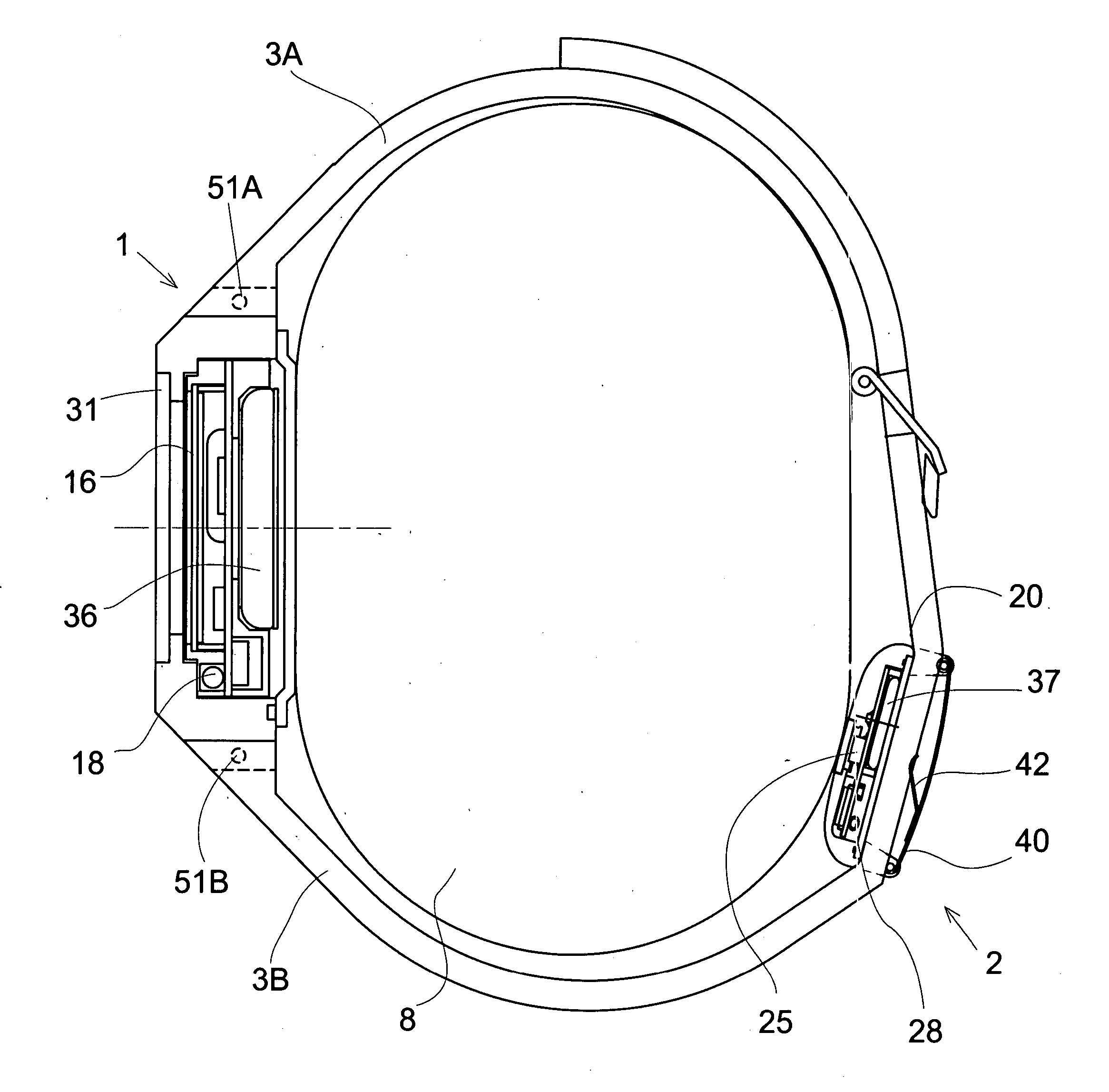
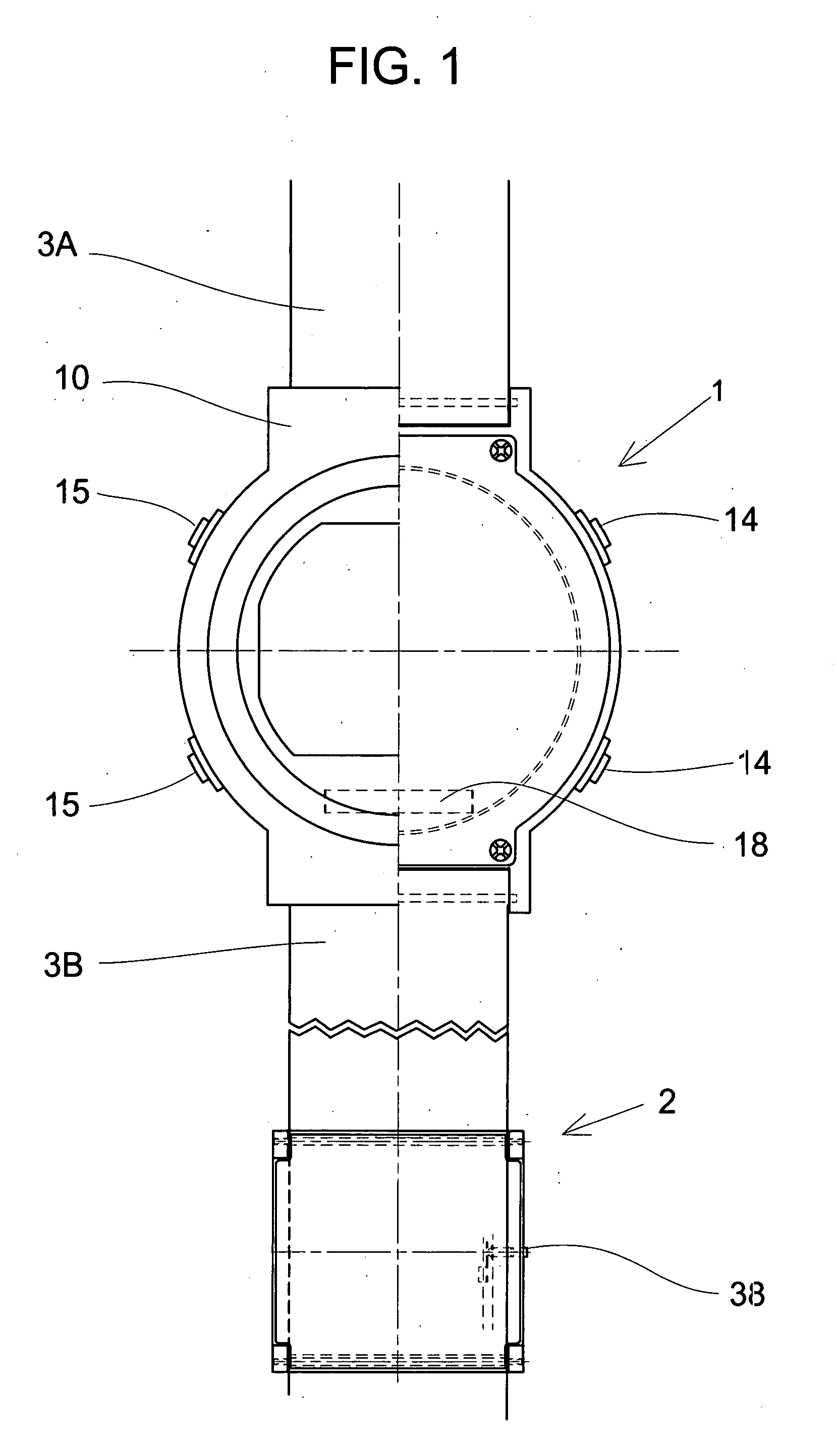
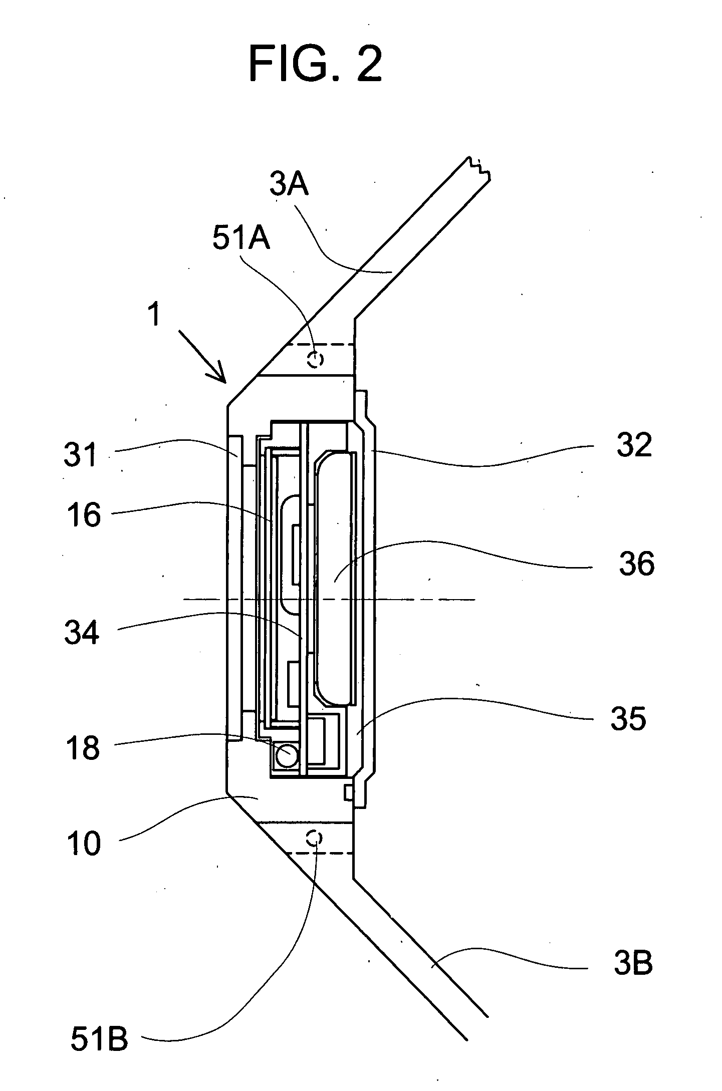
[0028] As shown in a plan view, of FIG. 1, of a main portion of a wristwatch type pulse measuring apparatus, a sectional view, of FIG. 2, of a timepiece head having been cut along a band longitudinal direction, a sectional view, of FIG. 3, of the wristwatch type pulse measuring apparatus having been shown while being cut along the band longitudinal direction under a state having been worn to a wrist 8, an enlarged sectional view, of FIG. 4, of a pulse sensor unit having been shown while being cut along the band longitudinal direction, and a block circuit diagram, of FIG. 10, of the wristwatch type pulse measuring apparatus, the present invention is the wristwatch type pulse measuring apparatus having been constituted by the pulse sensor unit 2 in which the pulse sensor 25 has been accommodated in the sensor housing 20, the timepiece head 1 at least possessing the display section 16 displaying the pulse number, and a band comprising one pair of band pieces 3A and 3B, and the pulse se...

embodiment 2

[0040] As shown in a plan view, of FIG. 5, of a main portion of a wristwatch type pulse measuring apparatus, a sectional view, of FIG. 6, of a timepiece head having been cut along a band longitudinal direction, a sectional view, of FIG. 7, of the wristwatch type pulse measuring apparatus having been shown *while being cut along the band longitudinal direction under a state having been worn to the wrist 8, enlarged sectional views, of FIG. 8 and FIG. 9, of a pulse sensor unit having been shown while being cut along the band longitudinal direction, and a block circuit diagram, of FIG. 11, of the wristwatch type pulse measuring apparatus, the present invention is the wristwatch type pulse measuring apparatus having been constituted by the pulse sensor unit 2 in which the pulse sensor 25 has been accommodated in the sensor housing 20, the timepiece head 1 at least possessing the display section 16 displaying the pulse number, and the band comprising one pair of band pieces 3A and 3B, an...


PUM


Abstract

A pulse measuring apparatus comprises a pulse sensor unit having a pulse sensor, a pulse measuring instrument having a display section for displaying a pulse number, and an arm wearing band fixed to the pulse measuring instrument and to which the pulse sensor unit is attached so as to be capable of adjusting its position in a longitudinal direction. A radio transmission section is disposed in the pulse sensor unit and a radio reception section is disposed in the measuring instrument, whereby data can be radio-transmitted from the pulse sensor unit to the measuring instrument. The data to be radio-transmitted is a pulse detection signal of the pulse sensor of the pulse sensor unit, or a pulse number obtained by calculation-processing the pulse detection signal by a signal processing section of the pulse sensor unit.

Description

BACKGROUND OF THE INVENTION [0001] 2. Field of the Invention [0002] The present invention relates to a pulse measuring apparatus, a so-called wristwatch type pulse measuring apparatus, which comprises a pulse sensor having been accommodated in a sensor housing, a pulse measuring instrument in which a display section processing a detection signal of the pulse sensor to thereby display a pulse number has, been accommodated in a measuring instrument case, and an arm wearing band which has been fixed to a measuring instrument case and to which the unit case has been attached so as to be adjustable in a longitudinal direction. [0003] 2. Description of the Prior Art [0004] In order to always measure the pulse number during a motion and the like to thereby make it an aim of a momentum, the wristwatch type pulse measuring apparatus has been developed. As shown in a block constitution diagram of FIG. 12, a conventional wristwatch type pulse measuring apparatus is constituted by a pulse measu...

Claims


Application Information

Patent Timeline
Patent Type & Authority Applications(United States)
IPC IPC(8): A61B5/02
CPCA61B5/0002A61B5/681A61B5/02438G04G21/025
Inventor NAKAMURA, HISAO
Owner SEIKO INSTR INC
Why Eureka
Try Eureka