Scatter correction method and apparatus for computed tomography imaging

a computed tomography and scatter correction technology, applied in the field of scatter correction of xray projection data in the computed tomography scanner system, can solve the problem of reducing the accuracy of the computed tomography value in three-dimensional spa

Active Publication Date: 2017-01-10
TOSHIBA MEDICAL SYST CORP
View PDF3 Cites 10 Cited by
  • Summary
  • Abstract
  • Description
  • Claims
  • Application Information

AI Technical Summary

Problems solved by technology

This scattered radiation greatly degrades the accuracy of a computed tomography (CT) value in three-dimensional imaging using a two-dimensional detector.

Method used


Image

  • Scatter correction method and apparatus for computed tomography imaging
  • Scatter correction method and apparatus for computed tomography imaging
  • Scatter correction method and apparatus for computed tomography imaging

Examples


Embodiment Construction

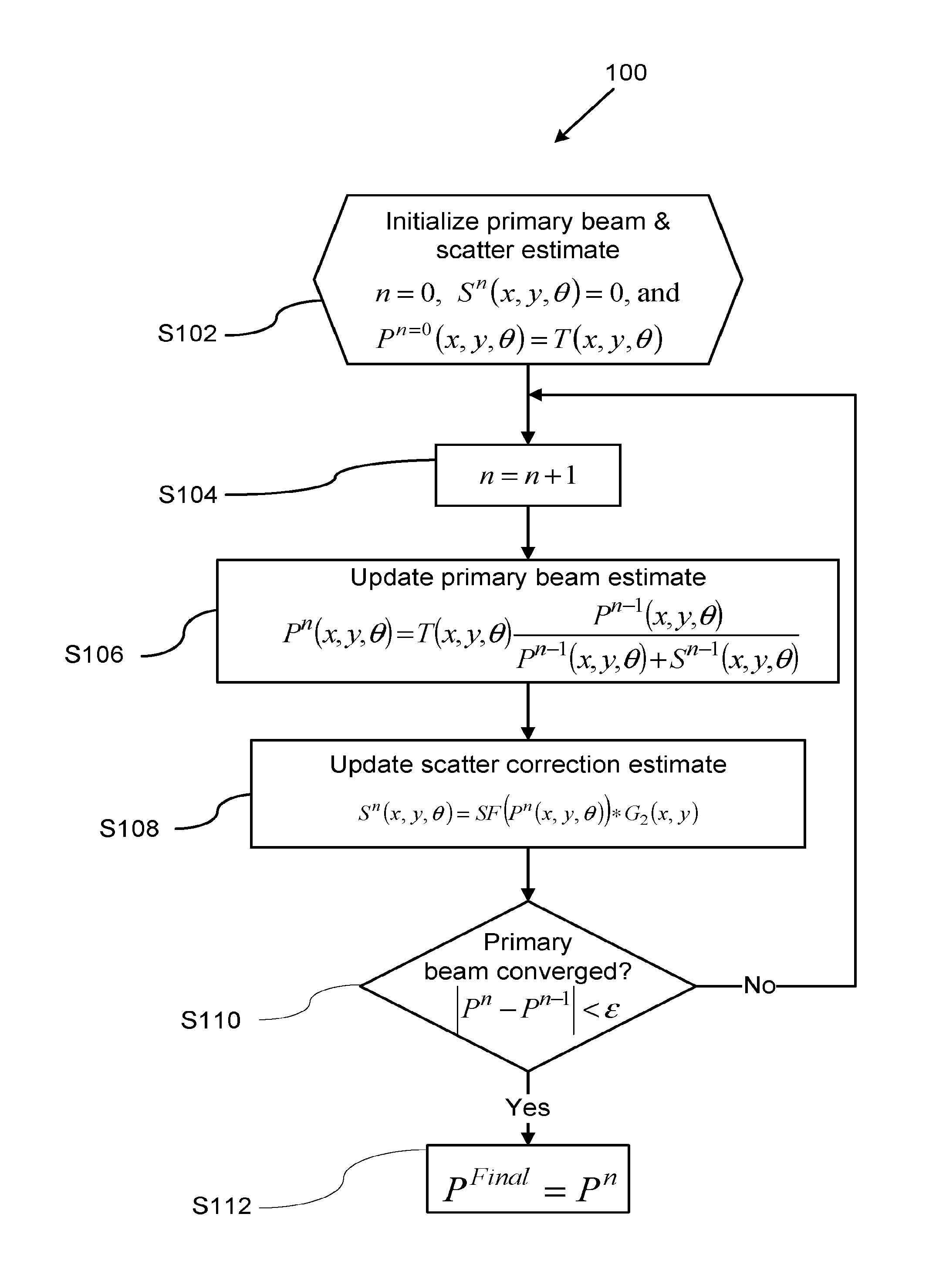
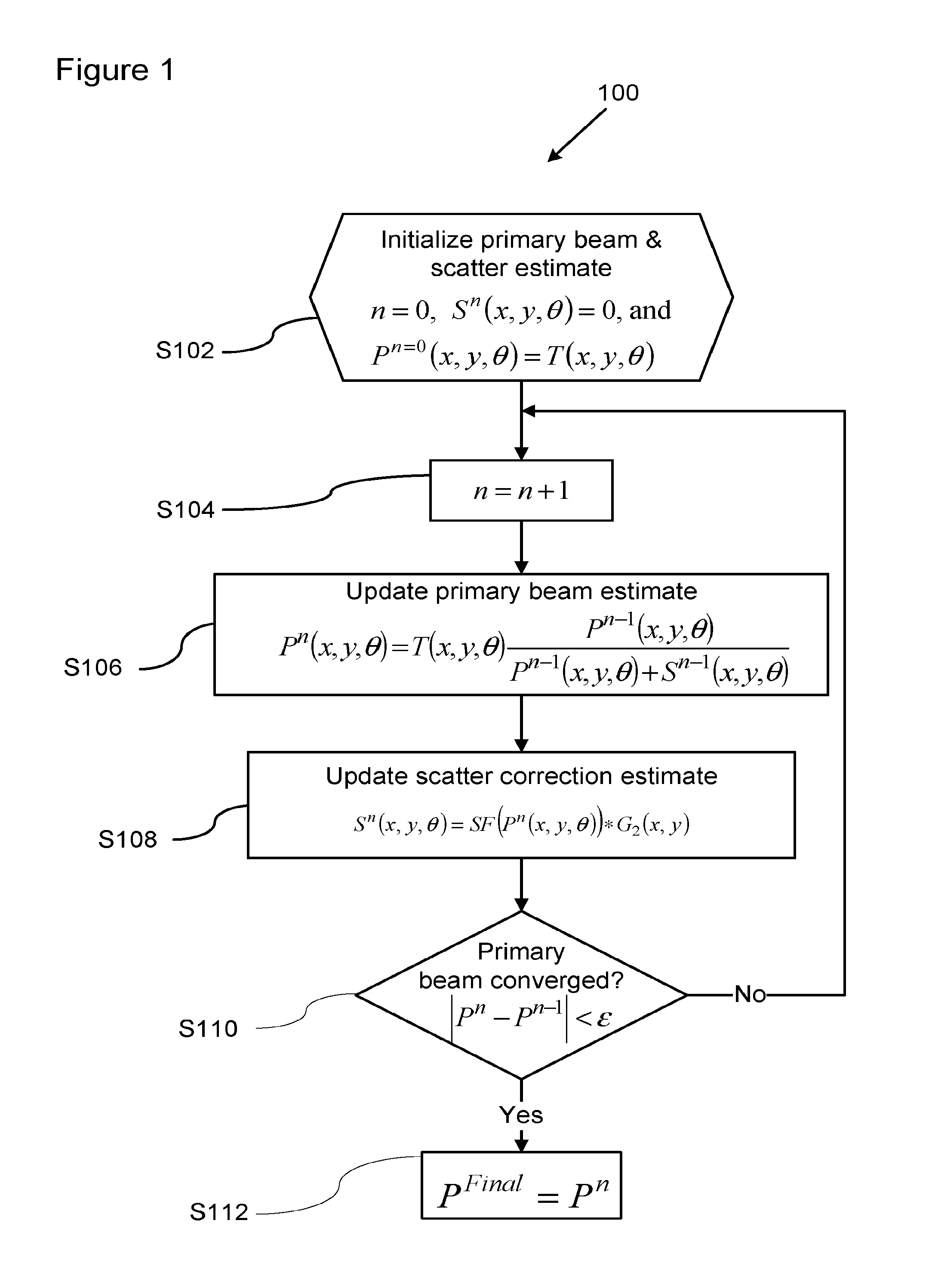
[0015]In one embodiment, there is provided an apparatus for scatter correction of projection data, the apparatus comprising processing circuitry configured to: (1) calculate a primary-beam estimate Pn, and (2) calculate a scatter estimate Sn using a convolution between a scattering function, SF(Pn), and a smoothing function G, wherein Pn is a current primary-beam estimate, Sn is a current scatter estimate, and SF(Pn) is a predetermined scatter function that is a function of the current the primary-beam estimate and is greater than zero over the range 0≦Pn<1.

[0016]In another embodiment, the processing circuitry is further configured calculate the primary-beam estimate according to

[0017]Pn=Pn-1⁢TPn-1+Sn-1,

wherein Pn-1 is a previous value of the primary-beam estimate, Sn-1 is a previous value of the scatter estimate, and T is the projection data.

[0018]In another embodiment, the processing circuitry is further configured to calculate the scattered estimate using the predetermined scatte...


PUM


Abstract

A method and apparatus to correct for scatter in projection data by successive approximations of a primary-beam estimate and a scatter estimate. The scatter estimate is calculated by convolving a scattering function, which is a function of the primary-beam estimate, with a smoothing function that includes Rayleigh scattering and Compton scattering terms. The scattering function is greater than zero in the limit that the primary-beam estimate goes to zero. The projection data can be X-ray computed tomography projection data, and the choice of scattering function has the benefit of reducing dark-band artefacts in reconstructed computed tomography images.

Description

BACKGROUND[0001]Field[0002]Embodiments described herein relate generally to a method of scatter correction of projection data, and more specifically to a method of scatter correction of X-ray projection data in a computed tomography scanner system.[0003]Description of the Related Art[0004]In general, an X-ray projection image contains many scattered radiation components. This scattered radiation greatly degrades the accuracy of a computed tomography (CT) value in three-dimensional imaging using a two-dimensional detector. A two-dimensional detector, like a flat-panel detector used in an X-ray diagnostic apparatus, uses a scattered-radiation-removing grid to suppress scattered radiation. The suppression of scattered radiation can be further improved by post processing the projection data using a scatter-correction algorithm. In an X-ray computed tomographic apparatus, a scatter-correction algorithm in conjunction with a scatter-suppressing grid yields superior images compared to scat...

Claims


Application Information

Patent Timeline
Patent Type & Authority Patents(United States)
IPC IPC(8): A61B6/03A61B6/00G06T11/00G06T7/00
CPCA61B6/5282A61B6/032G06T7/0012G06T11/005G06T2207/10081A61B6/4035A61B6/4441A61B6/5205
Inventor SILVER, MICHAEL D.
Owner TOSHIBA MEDICAL SYST CORP
Why Eureka
Try Eureka