Methods and apparatus for forming heat treated optical fiber
a technology of heat treatment and optical fiber, which is applied in the field of methods and apparatus for forming optical fiber, can solve the problems of unsatisfactory defects such as heat aging defects in the optical fiber, more susceptible to heat aging, and certain fiber refractive index profiles, so as to maintain the optical fiber within the treatment tension range, increase the rayleigh scattering, and reduce the effect of heat aging
- Summary
- Abstract
- Description
- Claims
- Application Information
AI Technical Summary
Benefits of technology
Problems solved by technology
Method used
Image
Examples
example 1
[0064] Using a draw furnace, a negative dispersion germania-doped optical fiber having a profile including a core and a ring as shown in FIG. 5 was drawn from a doped preform at a rate of 14 meters per second (m / s) with a tension of 150 grams. Thereafter, the fiber was cooled to 20° C. and then subjected to the heat aging test as described above. Following this test, the measured attenuation increase in the untreated fiber at 1550 nm was 0.0830 dB / km.
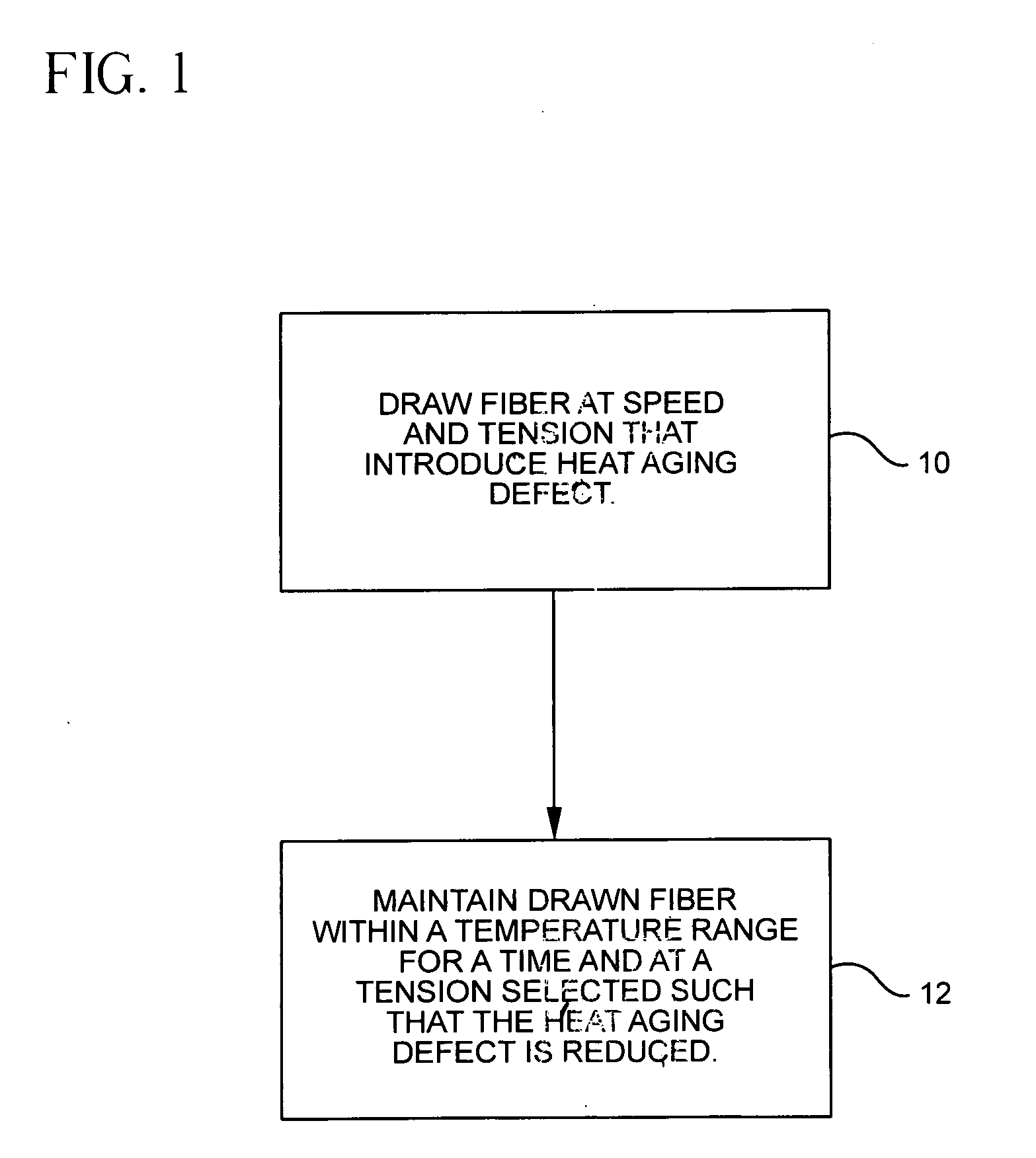
[0065] A second fiber was drawn from an identical preform in the same manner as described just above. The second fiber was passed through a treatment apparatus in accordance with the invention as described in FIG. 4 immediately after the fiber exited the draw furnace. The length and operating parameters of the treatment furnace were selected such that the temperature of the second fiber was maintained at a desired temperature for a desired amount of time. In particular, the length M of passage was about 0.615 m. Thus, the fiber was mai...
example 2
[0066] Using a draw furnace, a negative dispersion germania and fluorine doped optical fiber having a profile including a core, moat and a ring as shown in FIG. 6 was drawn from a preform at a rate of 14 meters per second (m / s) with a tension of 150 grams. Thereafter, the fiber was cooled to 20° C. and then subjected to the heat aging test as described above. Then testing revealed that the measured attenuation increase in the fiber at 1550 nm was 0.285 dB / km following heating for 20 hours at 200° C.
[0067] A second fiber was drawn from an identical preform in the same manner as described just above. The second fiber was subjected to the treatment apparatus and method in accordance with the invention described in FIG. 4 herein immediately after the fiber exited the draw furnace. The length and operating parameters of the treatment furnace were selected such that the temperature of the second fiber was maintained at the conditions identified in Example 1. Thereafter, the fiber was coo...
example 3
[0068] Using a draw furnace, a germania and fluorine doped silica glass optical fiber having a negative dispersion and dispersion slope and a profile as shown in FIG. 5 was drawn from a preform at a rate of 14 meters per second (m / s) with a tension of 150 grams. A helium forming gas was used in the draw furnace. Thereafter, the fiber was cooled to 20° C. and then subjected to the heat aging testing where the fiber is maintained at 200° C. for 20 hours. At the end of this period, the fiber was cooled to 20° C., the measured attenuation increase in the fiber at 1550 nm was 0.420 dB / km.
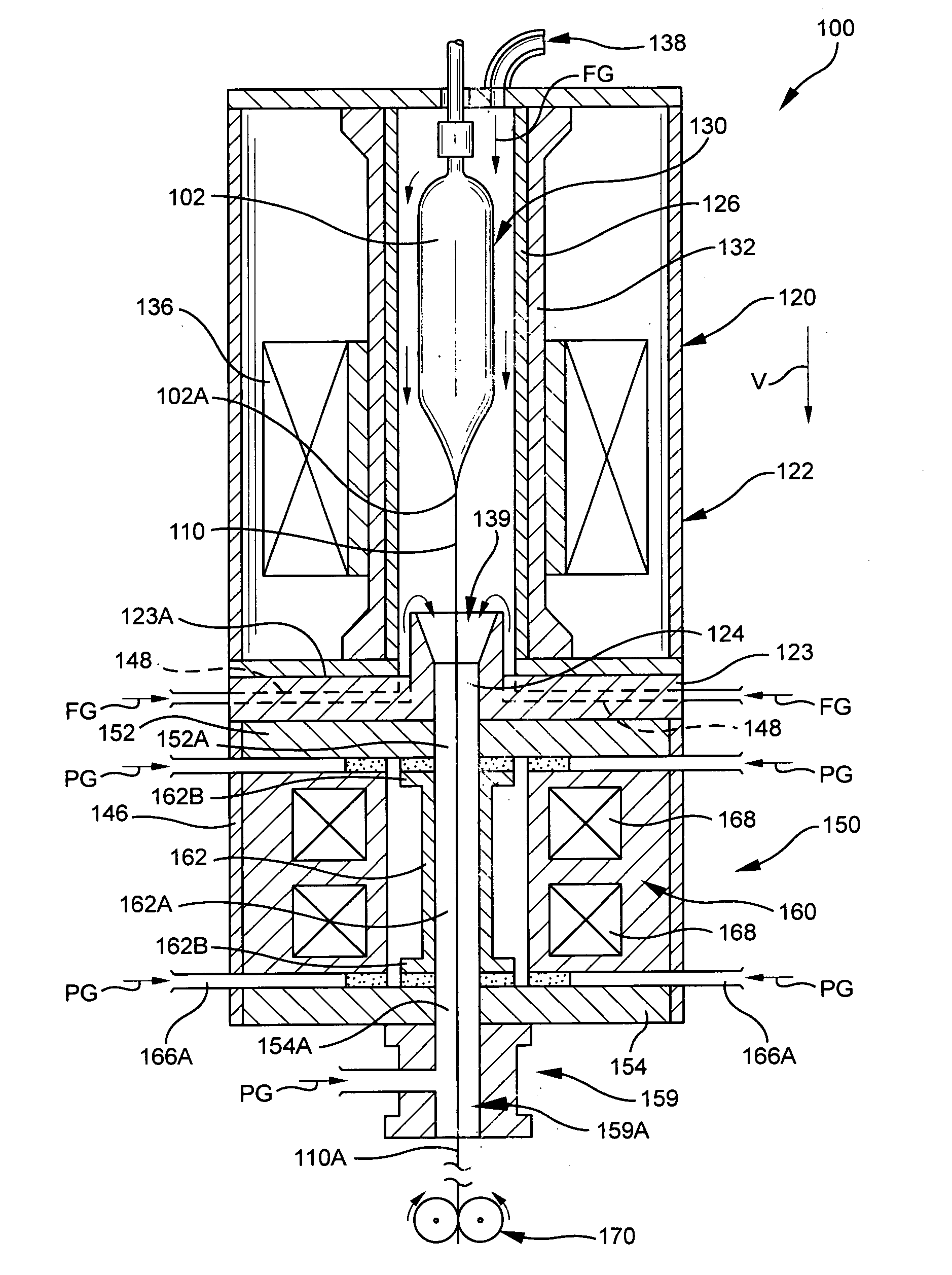
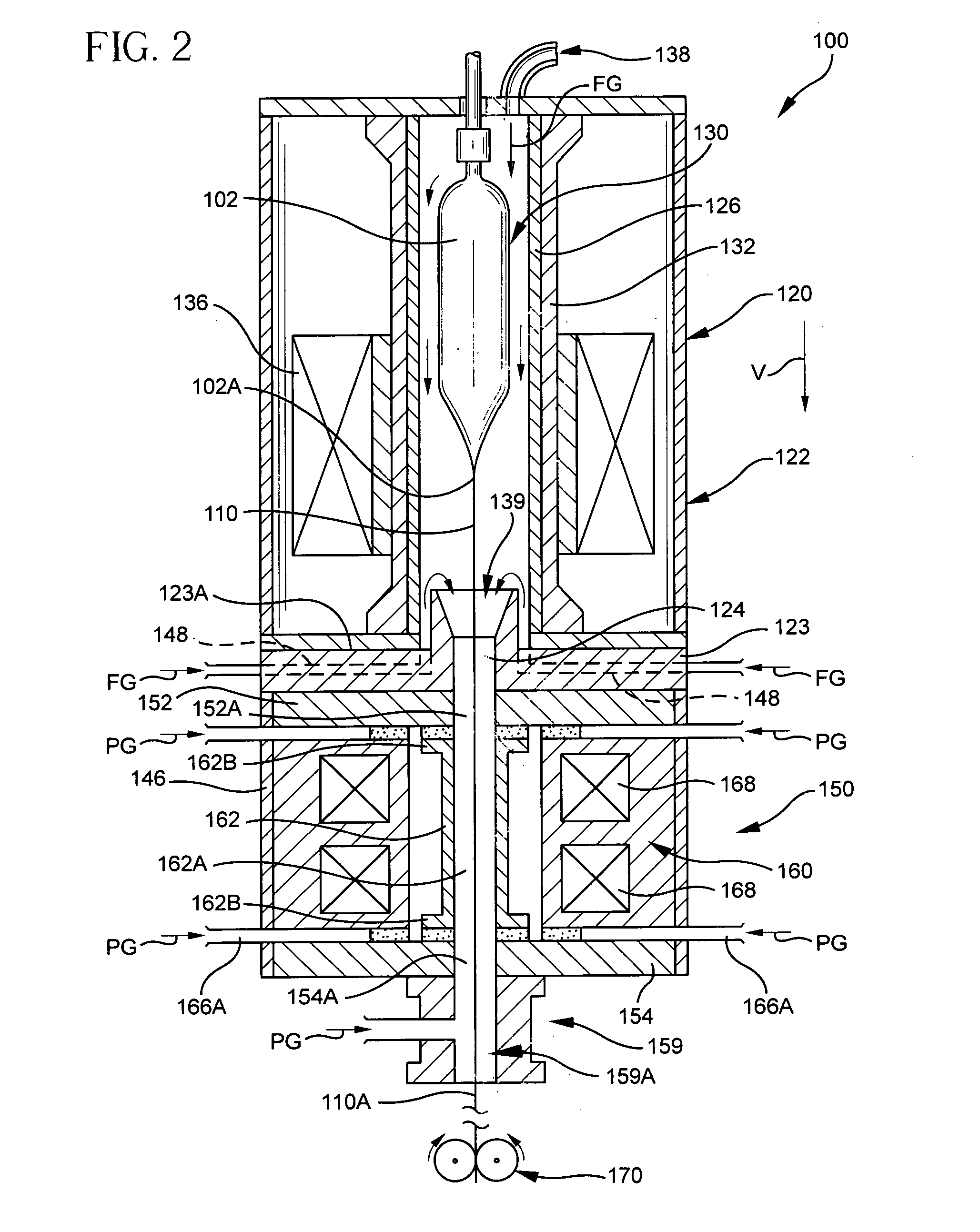
[0069] A second fiber was drawn in the same manner as described just above from an identical fiber. The second fiber was passed through a heated treatment apparatus as shown in FIG. 2 immediately after the fiber exited the draw furnace. The length of the muffle was 0.4 m and its inside diameter was 60 mm and the temperature was selected such that the temperature of the second fiber was maintained at fro...
PUM
| Property | Measurement | Unit |
|---|---|---|
| Time | aaaaa | aaaaa |
| Time | aaaaa | aaaaa |
| Speed | aaaaa | aaaaa |
Abstract
Description
Claims
Application Information
 - R&D
- Intellectual Property
- Life Sciences
- Materials
- Tech Scout
- Unparalleled Data Quality
- Higher Quality Content
- 60% Fewer Hallucinations
Browse by: Latest US Patents, China's latest patents, Technical Efficacy Thesaurus, Application Domain, Technology Topic, Popular Technical Reports.
© 2025 PatSnap. All rights reserved.Legal|Privacy policy|Modern Slavery Act Transparency Statement|Sitemap|About US| Contact US: help@patsnap.com


