
Motorised door lock actuator

a motorised and actuator technology, applied in the direction of non-mechanical control, building locks, constructions, etc., can solve the problems of increased force, inability to adapt to different door types, and difficulty for children or with reduced force in hands, etc., to achieve the effect of improving the art, reducing power, and being easy to opera

Active Publication Date: 2017-01-17
DANALOCK PATENT APS
View PDF30 Cites 17 Cited by
  • Summary
  • Abstract
  • Description
  • Claims
  • Application Information

AI Technical Summary

Benefits of technology

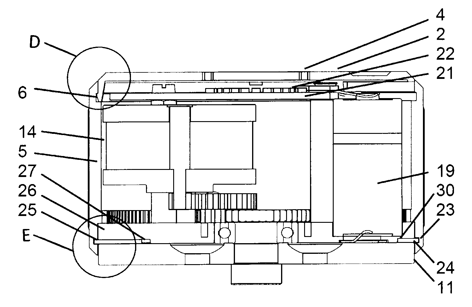
[0009]The actuation system comprises a cylindrical casing with a cylinder axis, the casing being delimited by a cylindrical handle and a rear plate and a circular front plate provided at opposite ends of the cylindrical handle. The rear plate is to be mounted towards the door. The cylindrical handle is operable with the hand and can be provided with a non-slip surface for easy manual grabbing. Typically, the cylindrical handle will have a circular outer cross sectional shape and a diameter of between 6 and 9 cm in order to be pleasant and easy to grab. Such size of handle makes it easy to manually operate a lock even with reduced power in the hands or with reduced motor skills in the fingers and hands, which often is the case for elderly people.
[0016]An advantageous technical solution is found in the following, wherein the cylindrical handle comprises inner teeth along the inner circumference of the cylindrical handle, the inner teeth being in interlocking cooperation with the gear wheel arrangement for being driven rotationally by the motor together with the pin receiver and for driving the pin receiver when manually rotating the cylindrical handle. By connecting the cylindrical handle to the pin receiver through the gearing, the force necessary to drive the cylindrical handle can be adjusted to very easy going. The latter is highly important for use by people with reduced power in their hands, such as elderly people, disabled, and children.
[0019]In order to provide a smooth rotation of the cylindrical handle, minimizing production costs and weight, the following type of bearing has been found useful. In this embodiment, a plain bearing is provided between the rear plate and the cylindrical handle for rotational support of the cylindrical handle by the rear plate. For example, the cylindrical handle comprises a circular groove that is movable on a ring, where the ring is provided with the rear plate of the casing. In a practical embodiment, the plain bearing comprises a recess in the rear plate and a largely ring-shaped slider arrangement sliding inside the groove. Thus, the largely ring shaped slider arrangement is connecting the groove and the recess for sliding movement between the groove and the recess about the slider arrangement when the cylindrical handle rotates relatively to the rear plate.
[0021]A simple but efficient arrangement is provided by the following. In this case, the recess has a first recess part with a first width along more than 3 / 4 of a circle, and the recess has a second recess part with a second, larger width on a remaining part of a circle. Thus, the recess has a constant width over more than 3 / 4 of a circle but then increases on the second recess part. In that second recess part, a screw or other type of fastener is provided for fastening one of the plates in that second recess part. Further, mounting of a number of plates in the first recess part is only possible by insertion of the number of plates from the second recess part into the first recess part due to the larger width of the first recess part. Fastening of a plate in the second recess parts by the screw or other type of fastener prevents the number of plates in the first recess part from escaping from it.
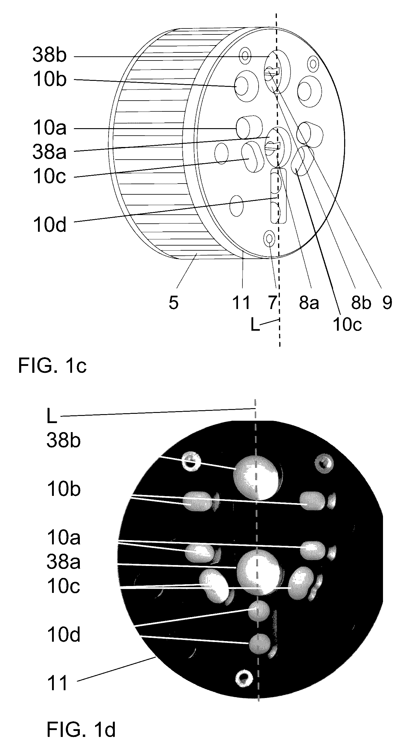
[0030]It can be mounted centred or off centred—yielding high flexibility with respect to mounting on different types of door lock with different dimensioning.
[0032]The shape and size facilitates grabbing around the handle and manual openings of doors. Especially for elderly people with reduced motoric skills in hands and fingers.

Problems solved by technology

In other words the lock is not versatile with respect to different door types.
The latter is a problem in case that the cylindrical door lock casing should be post-mounted on doors with already existing locks with a fixed position of the rotating lock pin from the lock inside the door.
This, in turn, requires additional force, which can be difficult for children or with persons with reduced force in their hands.

Method used


Image

  • Motorised door lock actuator
  • Motorised door lock actuator
  • Motorised door lock actuator

Examples


Embodiment Construction

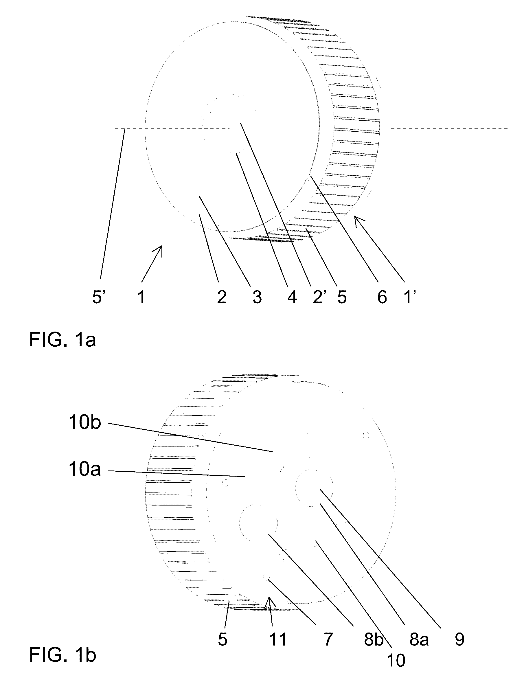
[0046]FIG. 1 illustrates a post-mount door lock actuation and control system in perspective view, where FIG. 1a is a front view and FIG. 1b is a rear view.

[0047]The actuation system 1 comprises a casing 1′ with a front plate 2 with a passive visual indicator 3 that shows the rotational position of the front plate 2. The front plate 2 is provided with a circle of small windows 4 through which or from which the light from diodes is transmitted. Optionally, corresponding diodes can be provided behind the windows or inside the windows. For example, a green light transmission indicates that the door is unlocked, whereas a red light indicates that the door is locked. The front plate is fastened by a snap-lock 6 to a cylindrical handle 5. The cylindrical handle 5 forms part of the casing 1′ and is mounted rotationally about a central rotation axis 5′ and can be used for opening the lock manually. If the door lock is opened electrically, the cylindrical handle 5 would be driven by a motor.

[...


PUM


Abstract

Actuation system for a door lock, where the door lock comprises a lock bolt driven by rotation of a lock pin that is functionally connected to the lock bolt. The actuation system comprises a cylindrical handle (5) with an outer diameter of between 6 and 9 cm. The system comprises a first pin receiver (8a) centred on the cylinder axis and a second pin receiver (8b) provided off centred between the cylinder axis and the cylindrical handle in order to be flexible with respect to post-mounting the actuating system on doors with already existing lock.

Description

FIELD OF THE INVENTION[0001]The present invention relates to a motorised lock for a door, for example apartment door. Especially, it relates to a post-mount actuation system for a door lock.BACKGROUND OF THE INVENTION[0002]In order to facilitate the operation of door locks, electrical motors are provided for post-mount on existing locks in doors. Retrofit motors for electrical actuation of a door lock are disclosed in US patent application No. 2010 0011822 and U.S. Pat. No. 4,901,545 as well as International patent application WO2012 177609, where a bezel is used for manually opening the lock but which also has a number keypad for operating it safely in an electronic way.[0003]Door locks that are operated electronically, for example via smartphones are gaining an increasing market share of electrical locks. An example is found on the Internet page www.August.com, disclosing a cylindrical electrical lock casing with a lock mechanism inside having a coaxial receiver for a rotating loc...

Claims


Application Information

Patent Timeline
Patent Type & Authority Patents(United States)
IPC IPC(8): E05B63/00E05B47/02E05B47/00
CPCE05B63/0056E05B47/02E05B2047/002E05B2047/0058E05B2047/0091E05B2047/0094Y10T70/7136
Inventor OVERGAARD, HENNING
Owner DANALOCK PATENT APS
Learn More