Motorised Door Lock Actuator

Active Publication Date: 2015-04-09
DANALOCK PATENT APS
View PDF24 Cites 42 Cited by
  • Summary
  • Abstract
  • Description
  • Claims
  • Application Information

AI Technical Summary

Benefits of technology

[0007]It is an objective of the invention to provide an improvement in the art. It is specifically an objective to provide a door lock actuation and control system that is easy to operate even for people with reduced power in their hands. A furthe

Problems solved by technology

In other words the lock is not versatile with respect to different door types.
The latter is a problem in case that the cylindrical door lock casing should be post-mounted on doors with already existing lock

Method used


Image

  • Motorised Door Lock Actuator
  • Motorised Door Lock Actuator
  • Motorised Door Lock Actuator

Examples


Example

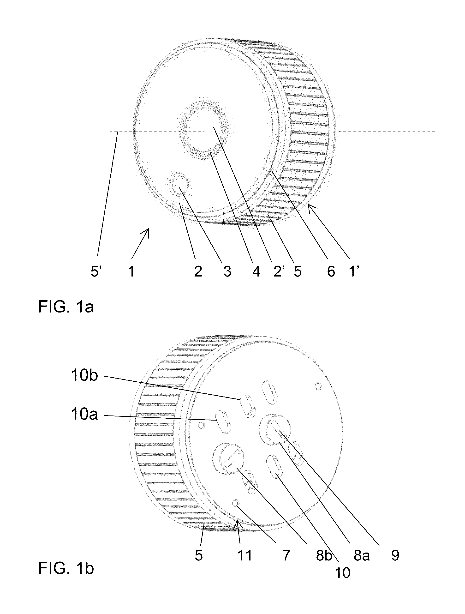
[0046]FIG. 1 illustrates a post-mount door lock actuation and control system in perspective view, where FIG. 1a is a front view and FIG. 1b is a rear view.

[0047]The actuation system 1 comprises a casing 1′ with a front plate 2 with a passive visual indicator 3 that shows the rotational position of the front plate 2. The front plate 2 is provided with a circle of small windows 4 through which or from which the light from diodes is transmitted. Optionally, corresponding diodes can be provided behind the windows or inside the windows. For example, a green light transmission indicates that the door is unlocked, whereas a red light indicates that the door is locked. The front plate is fastened by a snap-lock 6 to a cylindrical handle 5. The cylindrical handle 5 forms part of the casing 1′ and is mounted rotationally about a central rotation axis 5′ and can be used for opening the lock manually. If the door lock is opened electrically, the cylindrical handle 5 would be driven by a motor.

[...


PUM


Abstract

Actuation system for a door lock, where the door lock comprises a lock bolt driven by rotation of a lock pin that is functionally connected to the lock bolt. The actuation system comprises a cylindrical handle (5) with an outer diameter of between 6 and 9 cm. The system comprises a first pin receiver (8a) centred on the cylinder axis and a second pin receiver (8b) provided off centred between the cylinder axis and the cylindrical handle in order to be flexible with respect to post-mounting the actuating system on doors with already existing lock.

Description

FIELD OF THE INVENTION[0001]The present invention relates to a motorised lock for a door, for example apartment door. Especially, it relates to a post-mount actuation system for a door lock.BACKGROUND OF THE INVENTION[0002]In order to facilitate the operation of door locks, electrical motors are provided for post-mount on existing locks in doors. Retrofit motors for electrical actuation of a door lock are disclosed in US patent application No. 2010 0011822 and U.S. Pat. No. 4,901,545 as well as International patent application WO2012 177609, where a bezel is used for manually opening the lock but which also has a number keypad for operating it safely in an electronic way.[0003]Door locks that are operated electronically, for example via smartphones are gaining an increasing market share of electrical locks. An example is found on the Internet page www.August.com, disclosing a cylindrical electrical lock casing with a lock mechanism inside having a coaxial receiver for a rotating loc...

Claims


Application Information

Patent Timeline
IPC IPC(8): E05B47/00
CPCE05B47/0012E05B63/0056E05B47/02E05B2047/002E05B2047/0058E05B2047/0091E05B2047/0094Y10T70/7136
Inventor OVERGAARD, HENNING
Owner DANALOCK PATENT APS
Why Eureka
Try Eureka