
Multi-force sensing surgical instrument and method of use for robotic surgical systems

a surgical instrument and multi-force technology, applied in the field of multi-force sensing surgical instruments and robotic systems, can solve problems such as retina hemorrhage and tear, cornea striae, and the risk of applying excessive force to the retina

Active Publication Date: 2017-01-24
THE JOHN HOPKINS UNIV SCHOOL OF MEDICINE
View PDF27 Cites 144 Cited by
  • Summary
  • Abstract
  • Description
  • Claims
  • Application Information

AI Technical Summary

Benefits of technology

Enhances surgical precision and safety by providing accurate force feedback and motion guidance, reducing the risk of retina damage and improving the usability of robotic assistants in retinal microsurgery.

Problems solved by technology

The absence of force sensing raises the risk of applying excessive force on the retina, which can potentially cause retina hemorrhage and tearing.
Unsynchronized instrument motion can cause cornea striae, which distorts the view of the retina in the microscope.
Suboptimal ergonomics and fatigue impose further limitations on surgical performance.
Building both master and slave robots results in complex systems and high cost.
Furthermore, the surgeon's perception of the interaction between the slave robot and the patient is inadequate.
However, the workspace is constrained by the tracking system and scaled feedback of the human-imperceptible forces cannot be implemented.
The drawbacks include the large footprint and limited surgical application.
However, the stiffness of the Steady-Hand Eye Robot attenuates the user perceptible level of the sclera force, inducing undesired large sclera forces.
The drawback is that the force sensor cannot provide the sclera force value and the location where the sclera force is applied on the tool shaft.

Method used


Image

  • Multi-force sensing surgical instrument and method of use for robotic surgical systems
  • Multi-force sensing surgical instrument and method of use for robotic surgical systems
  • Multi-force sensing surgical instrument and method of use for robotic surgical systems

Examples


examples

[0109]All equation numbers in this example section refer to the equations introduced in this section, and not the equations in the previous section of this specification.

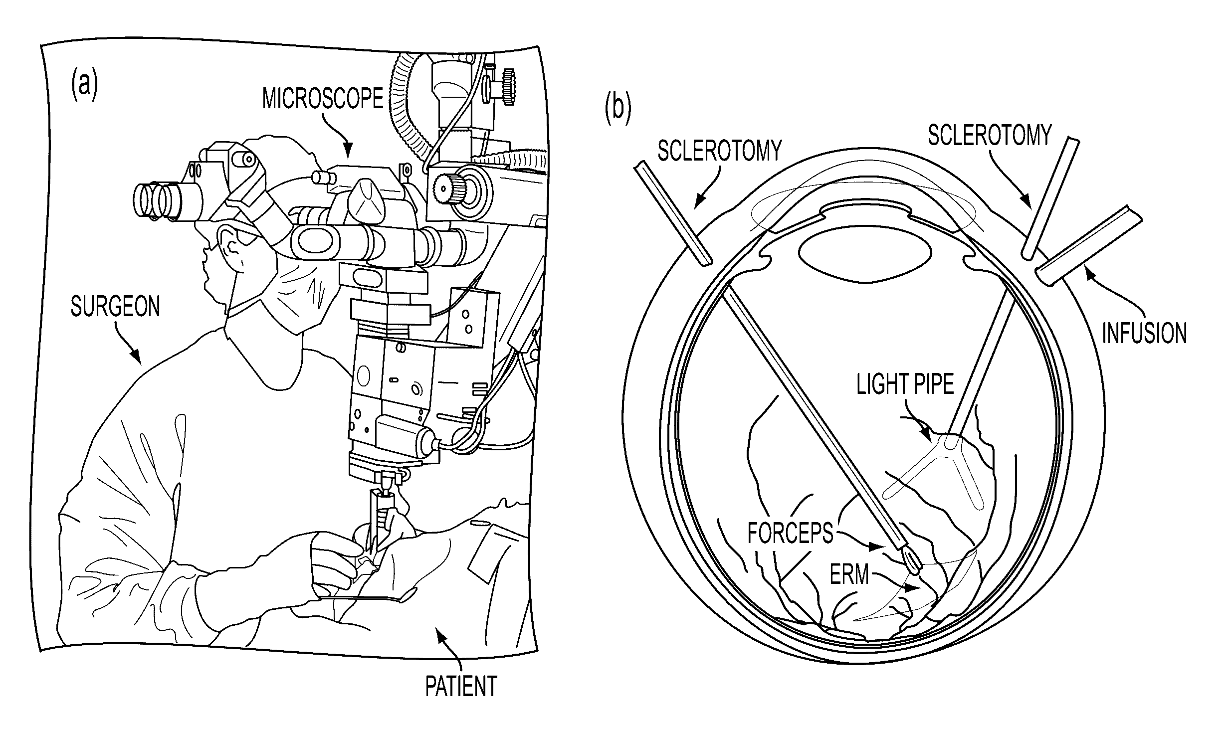
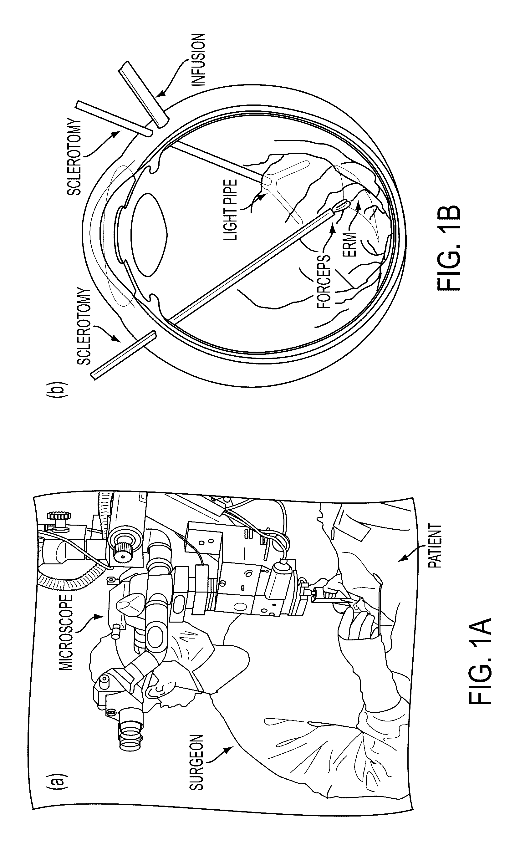
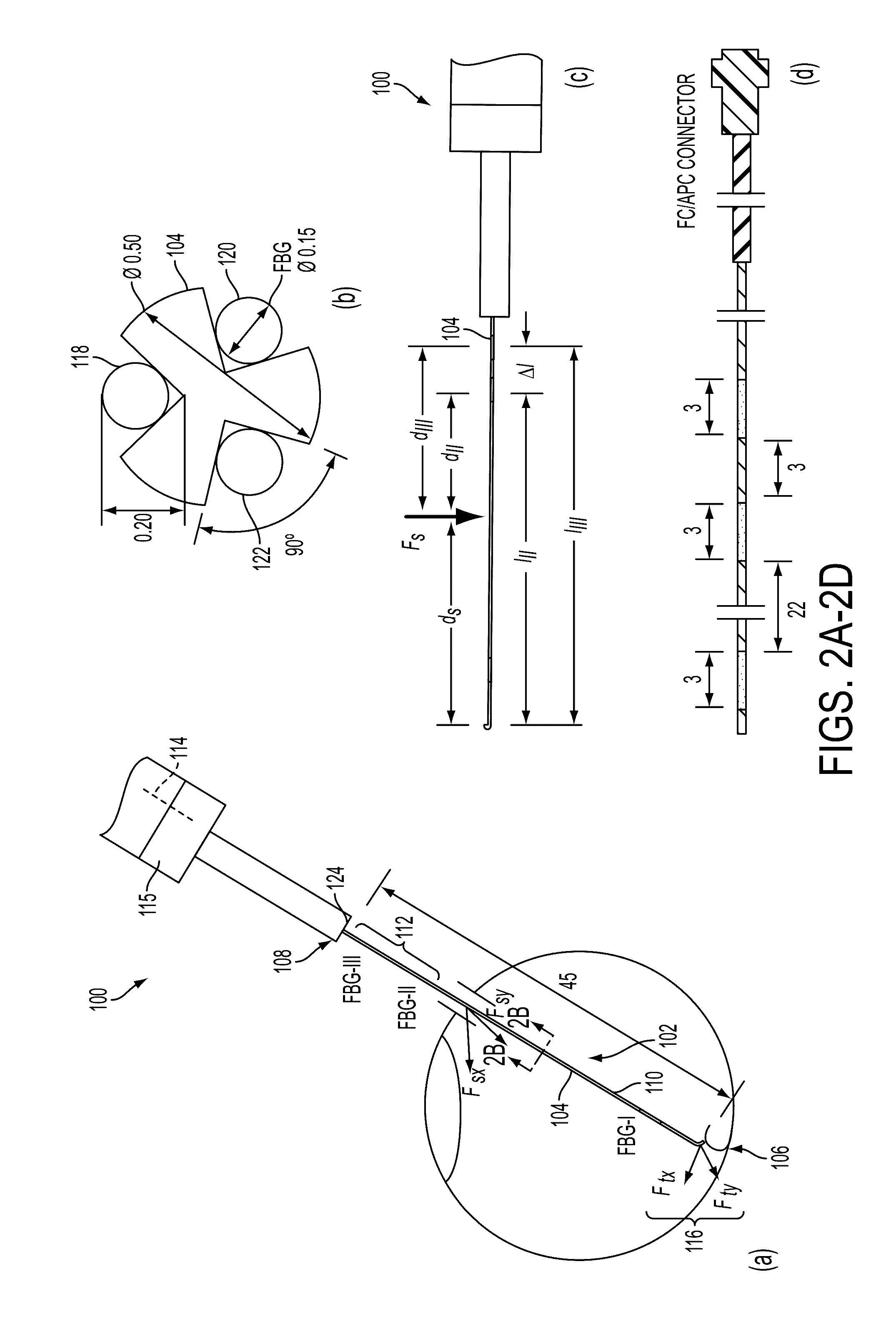
[0110]In following examples, we report a new design of a dual force sensing instrument according to an embodiment of the current invention that can sense not only the sclera force in transverse directions, but also the location of the sclera contact point on the tool shaft. This new dual force sensing instrument enables a variable admittance robot control to provide an intuitive robot behavior. By varying the robot admittance, the robot behavior can continuously transit from an adaptive virtual fixture mode that enforces RCM and adapts to the current location of the sclerotomy site, to a force scaling mode that provides scaled feedback of the sclera force as well as the ability to reposition the eye. Experiments are conducted to calibrate the new dual force sensing instrument, to calibrate the tool tip position with...


PUM

PropertyMeasurementUnit
Bragg wavelengthsaaaaaaaaaa

Abstract

A multi-force sensing instrument includes a tool that has a tool shaft having a distal end and a proximal end, a strain sensor arranged at a first position along the tool shaft, at least one of a second strain sensor or a torque-force sensor arranged at a second position along the tool shaft, the second position being more towards the proximal end of the tool shaft than the first position, and a signal processor configured to communicate with the strain sensor and the at least one of the second strain sensor or the torque-force sensor to receive detection signals therefrom. The signal processor is configured to process the signals to determine a magnitude and position of a lateral component of a force applied to the tool shaft when the position of the applied force is between the first and second positions.

Description

FEDERAL FUNDING[0001]This invention was made with Government support of Grant No. R01 EB 000526 and BRP Grant 1 R01 EB 007969, awarded by the Department of Health and Human Services, The National Institutes of Health (NIH). The U.S. Government has certain rights in this invention.BACKGROUND[0002]1. Field of Invention[0003]The field of the currently claimed embodiments of this invention relates to multi-force sensing instruments, robotic systems that incorporate the instruments, and methods of use.[0004]2. Discussion of Related Art[0005]Retinal microsurgery refers to intraocular surgical treatment of disorders related to the retina, vitreous, and macula of the eye. Typical diseases include retina detachment, macular degeneration, and diabetic retinopathy. Retinal microsurgery demands advanced surgical skills that are near or beyond natural human capabilities. During retinal microsurgery, a surgical microscope is placed above the patient to provide magnified visualization of the inter...

Claims


Application Information

Patent Timeline
Patent Type & Authority Patents(United States)
IPC IPC(8): A61B17/00G01L5/16G01L1/24A61F9/007
CPCA61B34/30A61B17/00234A61B34/10A61B90/06G01L1/246G01L5/166A61B34/35A61B34/72A61B34/76A61B34/77A61B2017/00345A61B2090/031A61B2090/064A61B2090/065A61B2090/066A61B2560/0247A61B2562/0266A61B2562/0271A61F9/007
Inventor HE, XINGCHIIORDACHITA, IULIANBALICKI, MARCINTAYLOR, RUSSELL H.
Owner THE JOHN HOPKINS UNIV SCHOOL OF MEDICINE
Learn More