Supercharge Your Innovation With Domain-Expert AI Agents!

Conveying apparatus and conveying system with cant surfaces

a conveying apparatus and cant surface technology, applied in the direction of manipulators, gripping heads, program-controlled manipulators, etc., can solve the problems of block and member in the vicinity of them becoming damaged prematurely, and achieve the effect of prolonging the li

Active Publication Date: 2017-01-24
DAIHEN CORP
View PDF11 Cites 0 Cited by
  • Summary
  • Abstract
  • Description
  • Claims
  • Application Information

AI Technical Summary

Benefits of technology

[0006]The present invention has been proposed in light of the above-described circumstances, and an object thereof is to provide a conveying apparatus whose lifetime can be extended.

Problems solved by technology

Accordingly, there is a possibility of the block and members in the vicinity thereof becoming damaged prematurely.

Method used


Image

  • Conveying apparatus and conveying system with cant surfaces
  • Conveying apparatus and conveying system with cant surfaces
  • Conveying apparatus and conveying system with cant surfaces

Examples


first embodiment

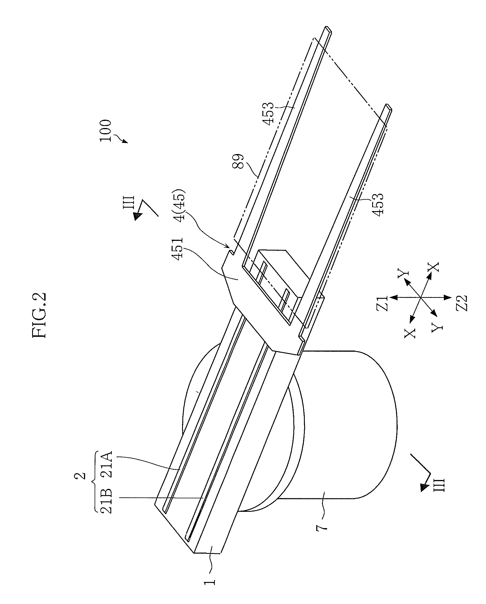
[0033]the present invention will be described below with reference to FIGS. 1 to 4.

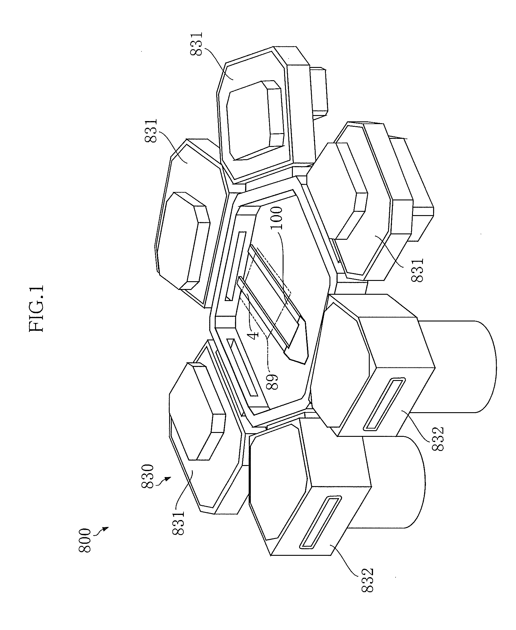
[0034]FIG. 1 is a perspective view of a conveying system according to the first embodiment of the present invention.

[0035]A conveying system 800 shown in this figure includes a conveying apparatus 100 (a portion of the configuration thereof is not shown in FIG. 1) and a workpiece housing mechanism 830.

[0036]The conveying apparatus 100 is a conveying robot for conveying a workpiece 89. The workpiece 89 is plate-shaped, and is a glass panel or a liquid crystal FPD substrate, for example.

[0037]The workpiece housing mechanism 830 is a mechanism for housing the workpiece 89. In the present embodiment, the workpiece housing mechanism 830 includes multiple workpiece storage apparatuses 831 and 832.

[0038]The workpiece storage apparatuses 831 are each for storing a workpiece 89. In the present embodiment, the workpiece storage apparatuses 831 (there are four of them) are each a chamber. More specifically, the ...

second embodiment

[0089]the present invention will be described below with reference to FIGS. 11 and 12.

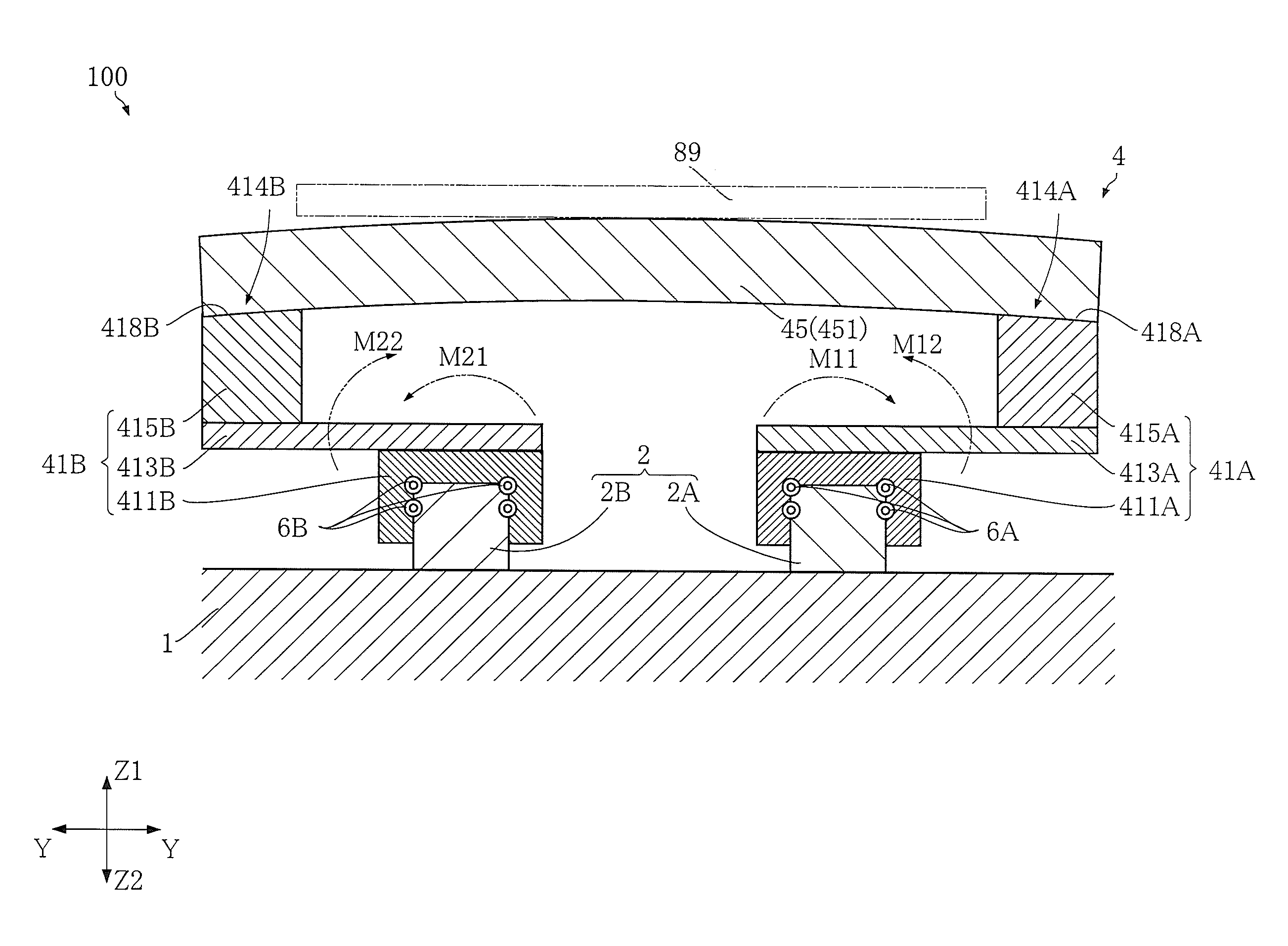
[0090]FIG. 11 is a cross-sectional diagram schematically showing a conveying apparatus according to the second embodiment of the present invention. FIG. 12 is a cross-sectional diagram showing a step in a manufacturing process for the conveying apparatus shown in FIG. 11.

[0091]A conveying apparatus 200 of the present embodiment differs from the above-described conveying apparatus 100 in that the first support 41A and the second support 41B are supported so as to be capable of moving in the first direction X relative to the same first guide portion 2A, and other aspects are similar to the conveying apparatus 100.

[0092]This configuration also has operation effects similar to the operation effects described in connection with the conveying apparatus 100. Note that although only two supports, namely the first support 41A and the second support 41B, are shown in FIG. 11, three or more supports may be pr...


PUM


Abstract

A conveying apparatus includes a guide mechanism and a moving body guided by the guide mechanism. The moving body includes a first support, a second support and a holding portion. The first support has a first engagement portion engaged with the guide mechanism. The first support, supported by the guide mechanism, is movable in a first direction. The second support has a second engagement portion engaged with the guide mechanism. The second support, supported by the guide mechanism, is movable in the first direction. The holding portion, supported by the first and the second supports, holds a workpiece. The first engagement portion receives a moment applied thereto by deformation of the moving body, where the moment is opposite in direction to a moment applied to the first engagement portion by a load of the workpiece held by the holding portion.

Description

BACKGROUND OF THE INVENTION[0001]1. Field of the Invention[0002]The present invention relates to a conveying apparatus and a conveying system.[0003]2. Description of Related Art[0004]In the process of manufacturing semiconductors and manufacturing liquid crystal panels, a conveying robot that can convey workpieces in a straight line is used to convey workpieces to and from a process chamber. In recent years, due to the increasing size of semiconductor wafers and liquid crystal panels, technology for using a linear guide to convey workpieces has been proposed in order to realize an accurate linear movement process (e.g., see JP-A-2005-125479). Two linear guide rails (hereinafter, referred to as rails) placed parallel to each other are provided with blocks that can move along the rails, hands are attached to the tops of the blocks via coupling members or the like, workpieces are placed on the hands, and the workpieces are conveyed linearly.[0005]When a workpiece is placed on a hand, a...

Claims


Application Information

Patent Timeline
Patent Type & Authority Patents(United States)
IPC IPC(8): H01L21/677B25J11/00B25J15/00B25J5/02
CPCB25J11/0095B25J5/02B25J15/0014H01L21/67706H01L21/67742H01L21/67748B25J9/06B25J11/00B65G49/061H01L21/677H01L21/67167H01L21/67201
Inventor MATSUO, HIDEKI
Owner DAIHEN CORP
Features
  • R&D
  • Intellectual Property
  • Life Sciences
  • Materials
  • Tech Scout
  • Unparalleled Data Quality
  • Higher Quality Content
  • 60% Fewer Hallucinations
Learn More