Stator arrangement and electrical generator

a technology of electrical generator and arrangement, which is applied in the direction of mechanical energy handling, magnetic circuit shape/form/construction, and association for rectification, etc., can solve the problem of shutdown of the whole electric energy generating machine, and achieve the effect of increasing the energy production

Active Publication Date: 2017-01-24
SIEMENS GAMESA RENEWABLE ENERGY AS
View PDF13 Cites 1 Cited by
  • Summary
  • Abstract
  • Description
  • Claims
  • Application Information

AI Technical Summary

Benefits of technology

[0012]When one of the first wire, the second wire, the first converter and the second converter fails or exhibits a malfunction the respective other converter and respective other wire may still be functioning and may still be used for operating the stator arrangement, in particular in an electric generator. Thereby, the delivery of the energy production may be increased.
[0049]By embodiments of the present invention cheaper magnets may be employed for the same performance of the electric generator. This is enabled by reducing the short circuit magneto motive force so that a lower coercivity is needed thereby a lower amount of Dysprosium is required for the permanent magnets leading to significantly cheaper magnets. Further, the radial thickness of the permanent magnets may be optimized or reduced with less limitation and force from the demagnetization perspective.

Problems solved by technology

If there is a fault in the converter or at one of the wires corresponding to one of the phases, the whole electric energy generating machine has to be shutdown.

Method used


Image

  • Stator arrangement and electrical generator
  • Stator arrangement and electrical generator
  • Stator arrangement and electrical generator

Examples


Embodiment Construction

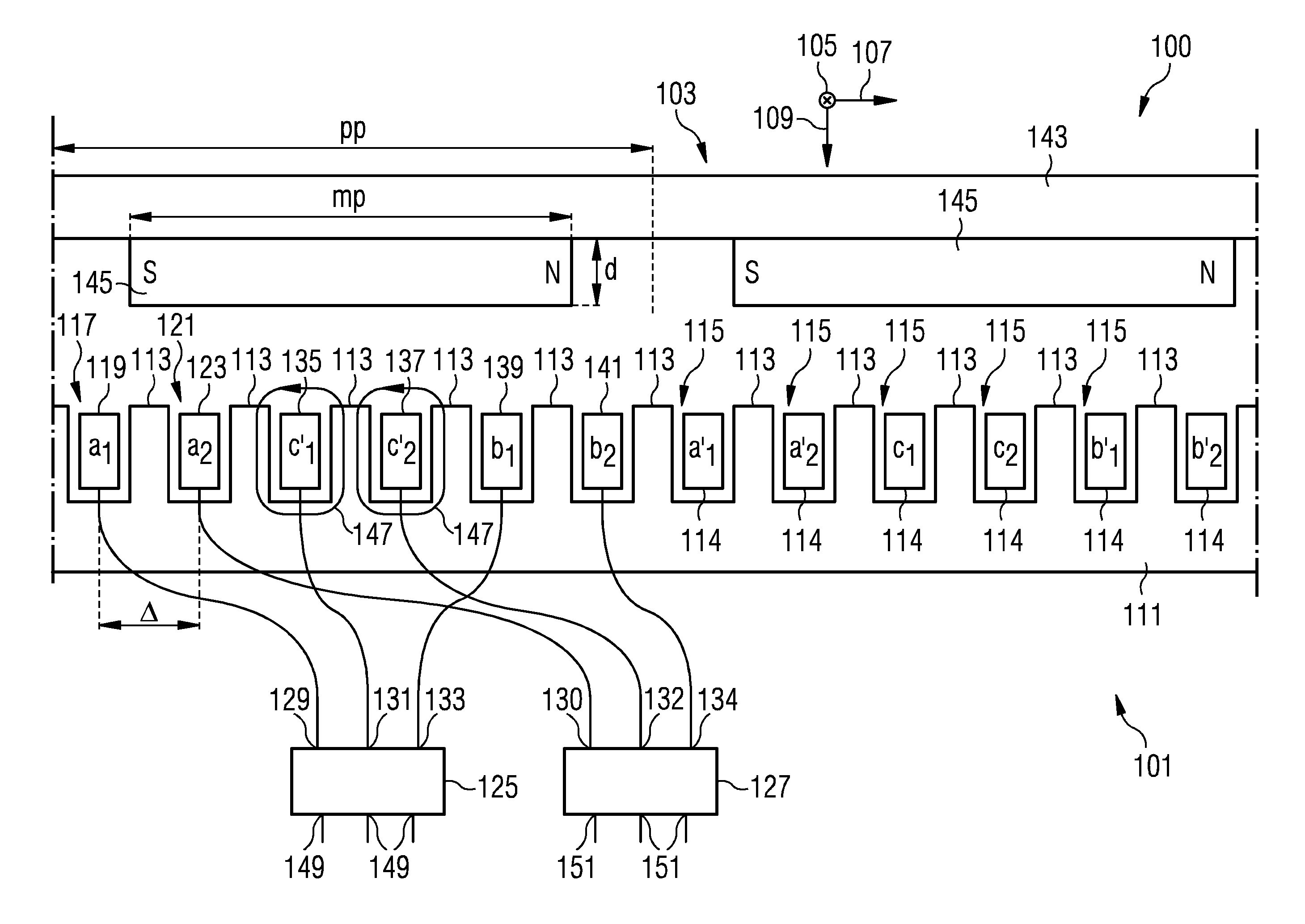
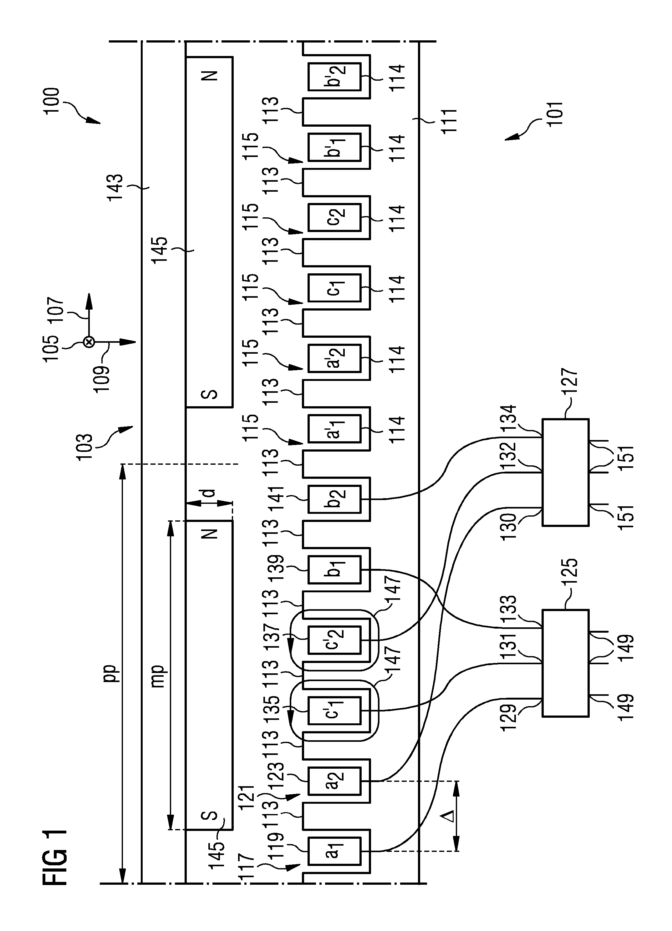
[0061]FIG. 1 schematically illustrates a portion 100 of an electric generator according to an embodiment of the present invention.

[0062]In particular, the illustration of the stator arrangement 101 comprises two stator poles, wherein the stator pole pitch pp is indicated in FIG. 1.

[0063]The portion 100 of the electric generator comprises a stator arrangement 101 and a rotor 103 rotating relative to the stator arrangement 101 around a rotation axis 105 which is oriented along an axial direction. The arrangement 100 is illustrated in FIG. 1 in a rolled-up version in which the circumferential direction 107 is bent from a circular direction to a straight direction for clarity. The axial direction is indicated by reference sign 105 (pointing into the drawing plane) and the radial direction is indicated by reference sign 109.

[0064]The stator arrangement 101 comprises a yoke 111 from which plural teeth 113 protrude radially outwards. The yoke 111 and the teeth 113 are manufactured from a m...


PUM


Abstract

A stator arrangement includes a stator extending in a circumferential direction and plural teeth alternating with plural slots arranged along the circumferential direction. A first wire is arranged in a first slot of the plural slots. A second wire is arranged in a second slot of the plural slots, wherein the second slot is circumferentially adjacent to the first slot. A first converter has an input terminal connected to the first wire and a second converter has an input terminal connected to the second wire.

Description

CROSS REFERENCE TO RELATED APPLICATIONS[0001]The present application claims priority to European Patent Application No. 12175750.4 EP filed Jul. 10, 2012, the entire content of which is hereby incorporated herein by reference.FIELD OF INVENTION[0002]The present invention relates to a stator arrangement and to an electromechanical transducer, in particular electric generator, comprising the stator arrangement, wherein parallel phases are arranged at circumferentially different positions of the stator.ART BACKGROUND[0003]A stator arrangement may be utilized for constructing an electric generator for producing electric energy from a rotational mechanical energy, such as a rotational energy provided by a wind turbine. The wind turbine shaft may drive a rotor having plural permanent magnets. The plural magnets may inductively couple to plural coils arranged at the stator, wherein the coils may correspond to two or more electric phases. The two or three or more phases or the corresponding...

Claims


Application Information

Patent Timeline
Patent Type & Authority Patents(United States)
IPC IPC(8): H02P9/02H02K3/28H02K11/00H02K11/04H02K7/18
CPCH02P9/02H02K3/28H02K11/046H02K7/1838H02K2213/03H02K2213/06H02K2213/12H02K1/16
Inventor KIMIABEIGI, MOHAMMAD
Owner SIEMENS GAMESA RENEWABLE ENERGY AS
Why Eureka
Try Eureka