
Motorcycle

a technology for motorcycles and motor vehicles, applied in the field of motorcycles, can solve problems such as affecting shape, and achieve the effects of increasing the capacity of the fuel tank, and improving the workability of attaching lead wires and the like to the fuel injection devi

Active Publication Date: 2017-01-31
HONDA MOTOR CO LTD
View PDF5 Cites 2 Cited by
  • Summary
  • Abstract
  • Description
  • Claims
  • Application Information

AI Technical Summary

Benefits of technology

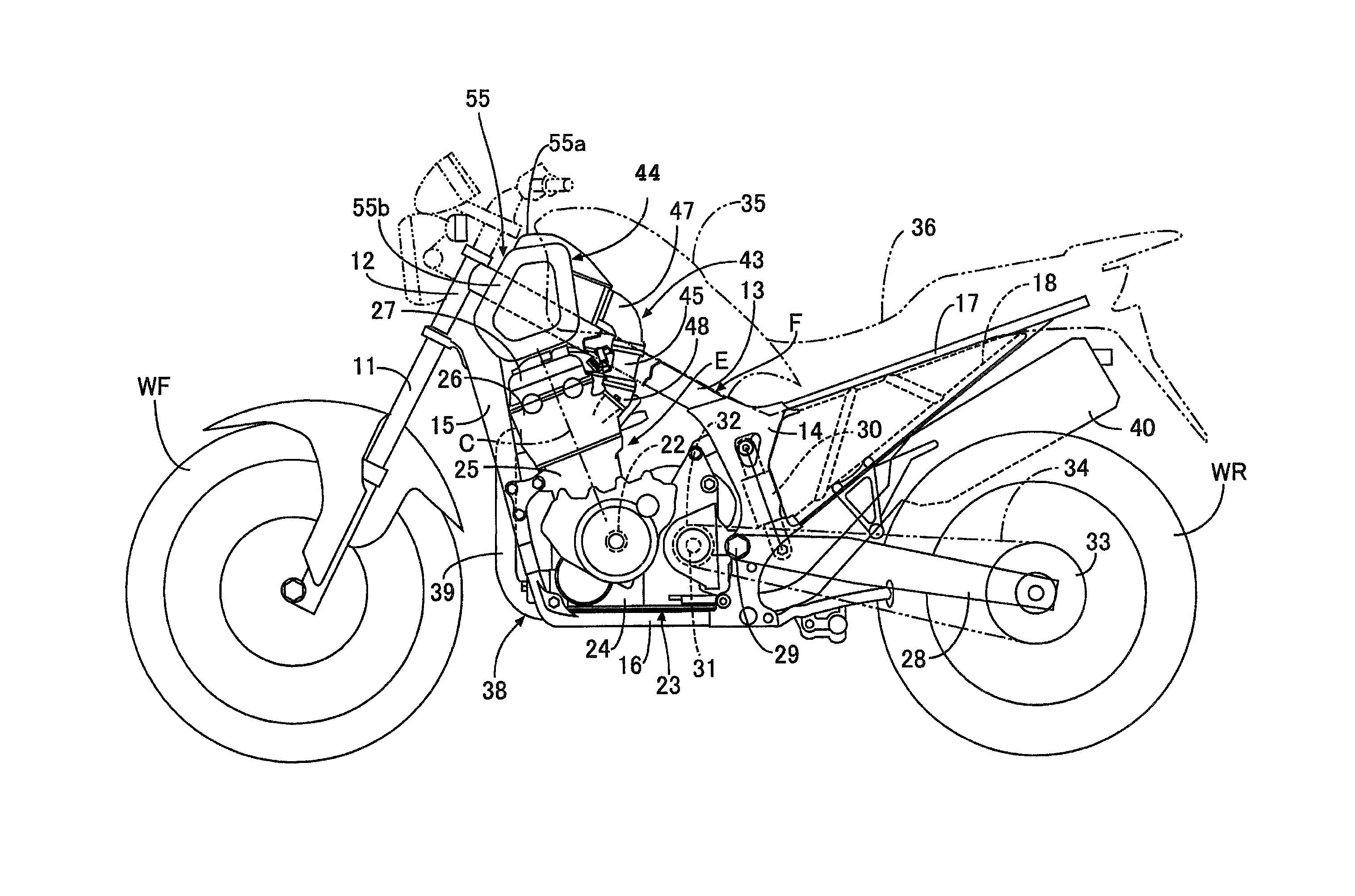
The present invention aims to improve the arrangement of fuel tank and air cleaner in a vehicle body. This results in securing the capacity of the fuel tank and preventing the knees of passengers from coming into contact with the air cleaner. Additionally, it eliminates the necessity of a layout space for the fuel injection device behind the throttle device, further increasing the capacity of the fuel tank. The fuel injection device is arranged in a posture extending in the vertical direction to secure a clearance between the cylinder head and the fuel injection device, improving workability in attaching lead wires and the like to the fuel injection device. The most-rear end of the air cleaner is arranged in a forward direction of the most-rear end of the cylinder block, which secures space behind the cylinder block and allows various components to be arranged close to each other behind the cylinder block, contributing to the centralization of mass. The capacity of the air cleaner is secured because it includes the pair of left and right extension portions that extend outwardly on both sides in the vehicle width direction in such a manner so as to straddle the pair of left and right main frames extending rearwardly from the head pipe.

Problems solved by technology

Such a large air cleaner poses a problem of influencing the shape and the layout space of a fuel tank to be arranged behind the air cleaner.

Method used


Image

  • Motorcycle
  • Motorcycle
  • Motorcycle

Examples


Embodiment Construction

[0033]Embodiments of the present invention are described with reference to the accompanying drawings. In the following description, front, rear, left, right, upward and downward indicate directions viewed from a passenger who rides on the motorcycle.

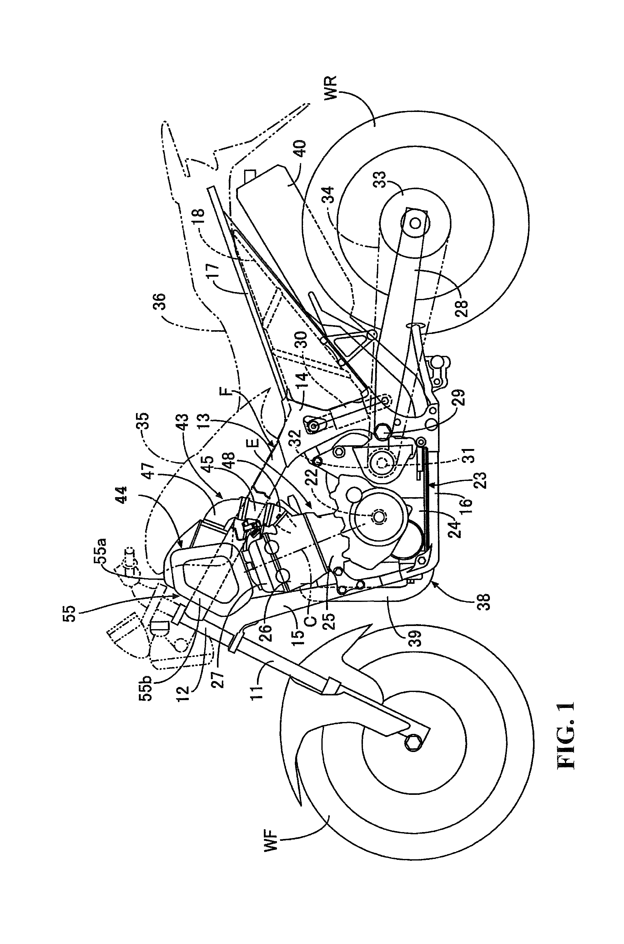
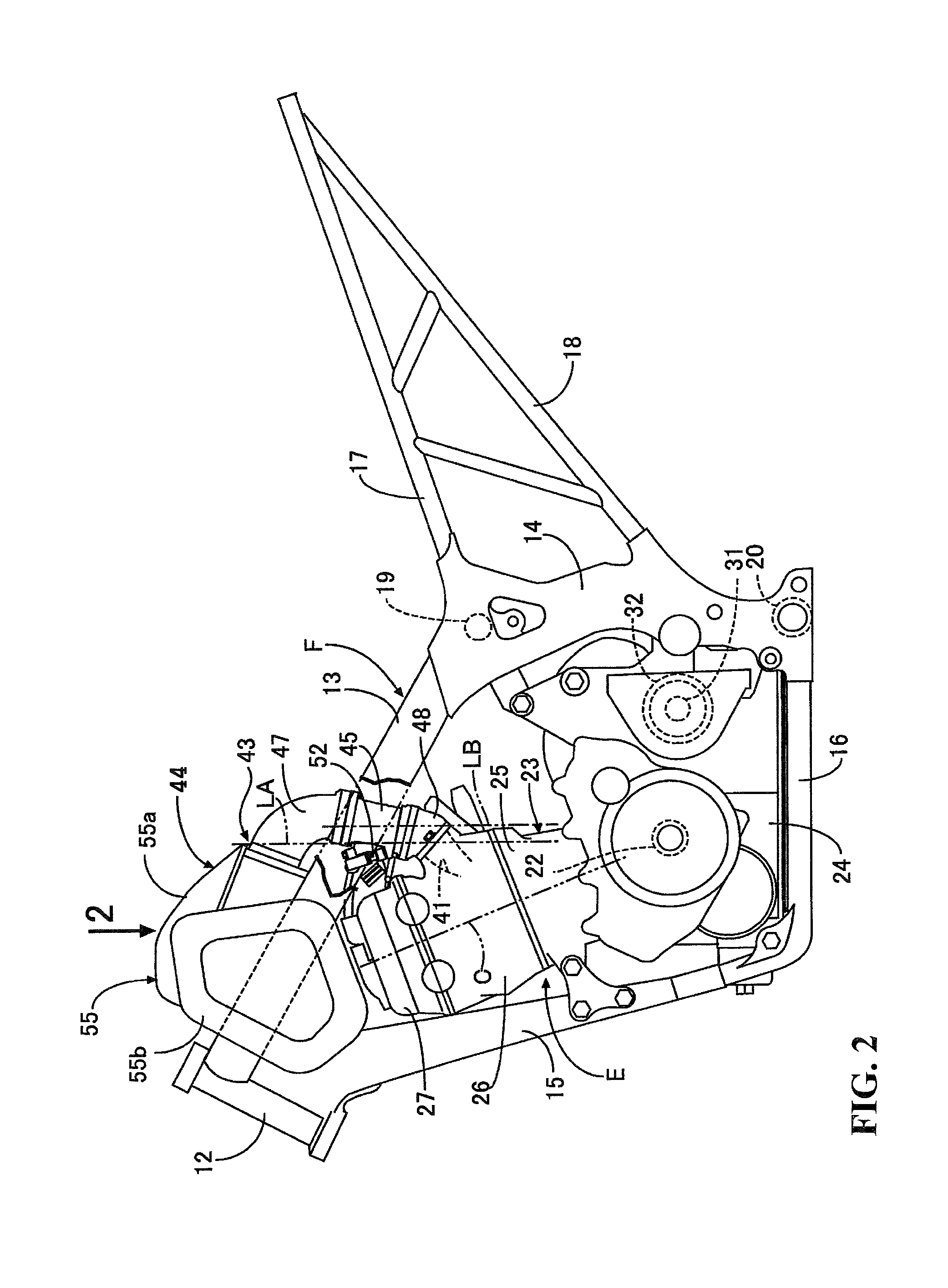
[0034]A first embodiment of the present invention is described with reference to FIGS. 1 to 5. To begin with, in FIGS. 1 and 2, a vehicle body frame F of this motorcycle includes a head pipe 12 supporting a front fork 11 in a steerable manner. The front fork 11 rotatably supports a front wheel WF at a lower end portion thereof. A pair of left and right main frames 13 extend downwardly and rearwardly from the head pipe 12 with a pair of left and right pivot frames 14 extending downwardly from rear ends of the main frames 13. A down frame 15 extends downwardly and rearwardly from the head pipe 12 while inclining at a steeper angle than the main frames 13 incline. A pair of left and right lower frames 16 connect a rear end of the down frame...


PUM


Abstract

An air cleaner positioned above a cylinder head is connected to an intake port of the cylinder head through a connecting tube, a throttle device, and an insulator. An insulator attachment surface is formed in a rear-side wall of a cylinder head such that the insulator attachment surface is inclined to extend in a forward direction while extending upwardly. An insulator is formed in such an arc shape in a side view wherein a flow direction of air flowing inside the insulator is directed more in a forward direction as the air approaches the cylinder head. A throttle device having an intake passage thereof directed in a vertical direction is connected to the insulator. A connecting tube is formed to curve in such a shape that the connecting tube has its upstream end opened in a forward direction and is rounded outwardly in an obliquely rearward direction.

Description

CROSS-REFERENCE TO RELATED APPLICATIONS[0001]The present application claims priority under 35 USC 119 to Japanese Patent Application No. 2013-015700 filed Jan. 30, 2013 the entire contents of which are hereby incorporated by reference.BACKGROUND OF THE INVENTION[0002]1. Field of the Invention[0003]The present invention relates to a motorcycle wherein an engine main body includes a cylinder axis that is inclined upwardly and forwardly. A fuel tank is arranged above the engine main body. The engine and the fuel tank are mounted on a vehicle body frame. A cylinder head forming a part of the engine main body is provided with an intake port. An air cleaner is arranged above the cylinder head and is connected to the intake port through a throttle device including an intake passage. A connecting tube is provided between the throttle device and the air cleaner with a tubular insulator being provided between the throttle device and the cylinder head.[0004]2. Description of Background Art[000...

Claims


Application Information

Patent Timeline
Patent Type & Authority Patents(United States)
IPC IPC(8): F02M35/16H01T13/02F02B67/00F02M35/04
CPCF02M35/048F02M35/162B62J99/00B62K11/00F02M35/04
Inventor OZAKI, YOSHINOBUIMAI, RYOJI
Owner HONDA MOTOR CO LTD
Learn More