System and method for determining the position of objects in a radiation room for radiation therapy

a radiation therapy and object technology, applied in the direction of diagnostics, therapy, instruments, etc., can solve the problems of insufficient and comprehensive monitoring of the position of the patient body, structural complex devices therein, and de 297 24 767 u1 devices also structural complex, etc., to achieve short treatment time, avoid additional radiation load, and the effect of high accuracy

Active Publication Date: 2017-01-31
HOFMANN KARSTEN
View PDF14 Cites 7 Cited by
  • Summary
  • Abstract
  • Description
  • Claims
  • Application Information

AI Technical Summary

Problems solved by technology

In DE 103 42 202 A1, only a few individual points on the skin of the patient are captured so that an exact and comprehensive monitoring of the position of the patient body is not satisfactorily possible.
Moreover, the device therein is structurally complex, since the distance measuring devices must also be housed in the radiation room.
The device in DE 297 24 767 U1 is also structurally complex since the light transmitters and cameras used for the measurements must also be housed in the radiation room.
The points marked on the skin of the patient for positioning the patient for today's modern radiation therapy no longer meet the accuracy requirements with high doses per radiation fraction and small radiation fields at high field gradients.
Radiation therapy without multi-modal image registration methods with rigid (RIR) or elastic (deformable DIR) algorithms and image positioning methods is now unthinkable.
Nonetheless, current radiation therapy cannot get past the most exact possible initial positioning of the patient with laser lines.
If the initial patient position is not sufficiently close to the reference position due to faulty patient positioning, these optimization methods can deliver incorrect results.
This can lead to incorrect positioning information (displacement vectors) and thus to unplanned irradiation of the patient.
The capturing of CB-CT images before each radiation fraction takes a lot of time and the radiation load on the healthy organs of the patient increases with each image, which can lead to subsequent radiation-induced cancer.
Even the slightest deviations, as can result for example due to different patient weights, have an adverse effect on the quality of the radiation fraction in today's high-precision radiation procedures.

Method used


Image

  • System and method for determining the position of objects in a radiation room for radiation therapy
  • System and method for determining the position of objects in a radiation room for radiation therapy
  • System and method for determining the position of objects in a radiation room for radiation therapy

Examples


Embodiment Construction

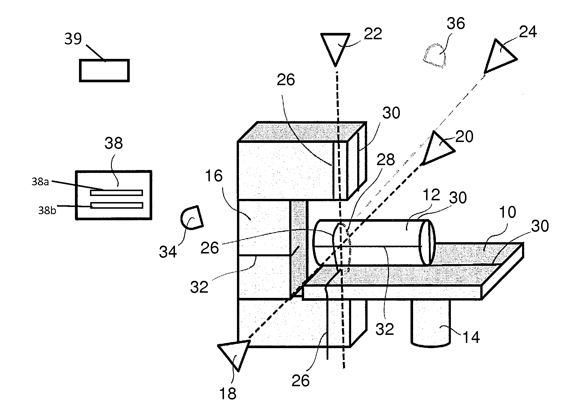
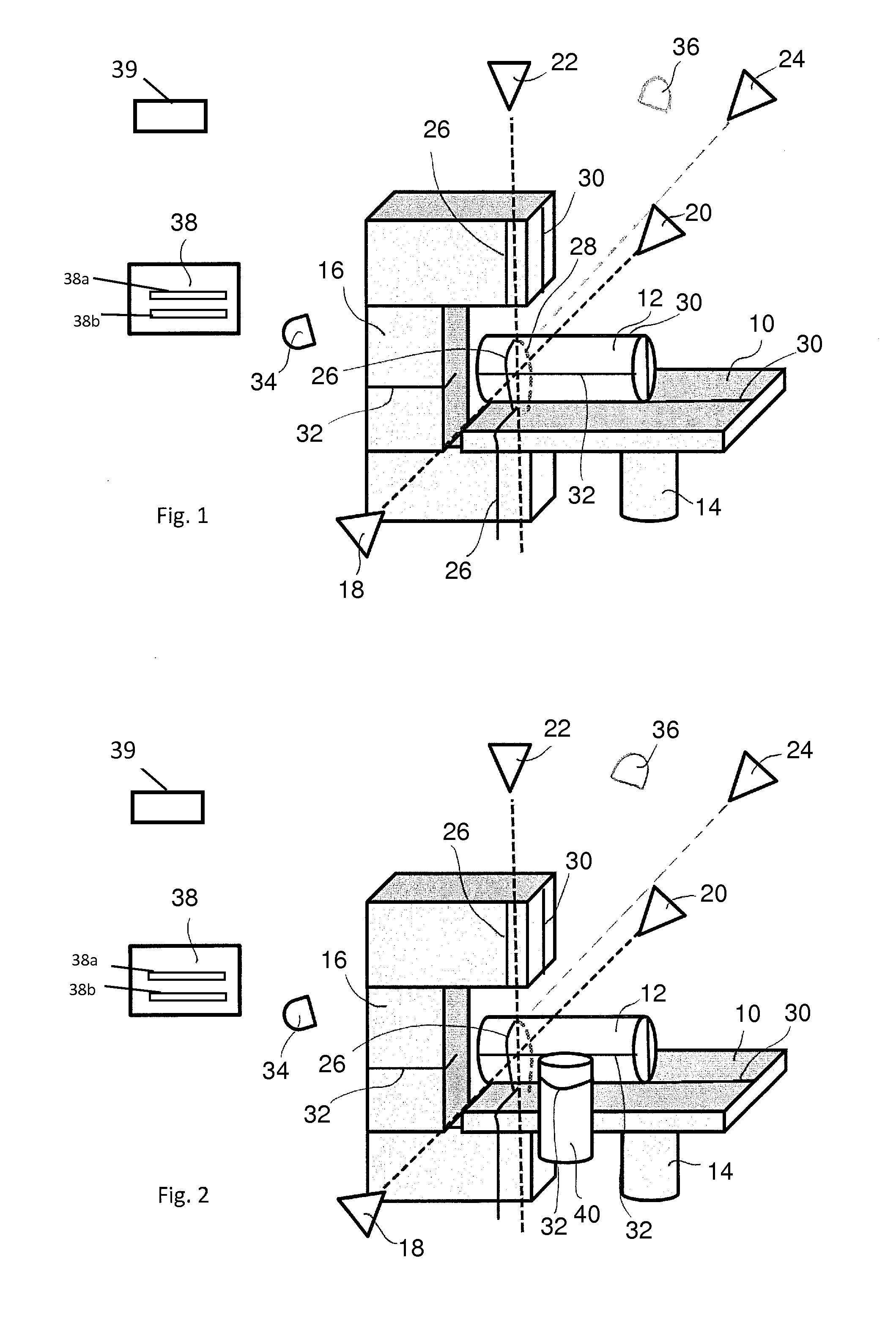
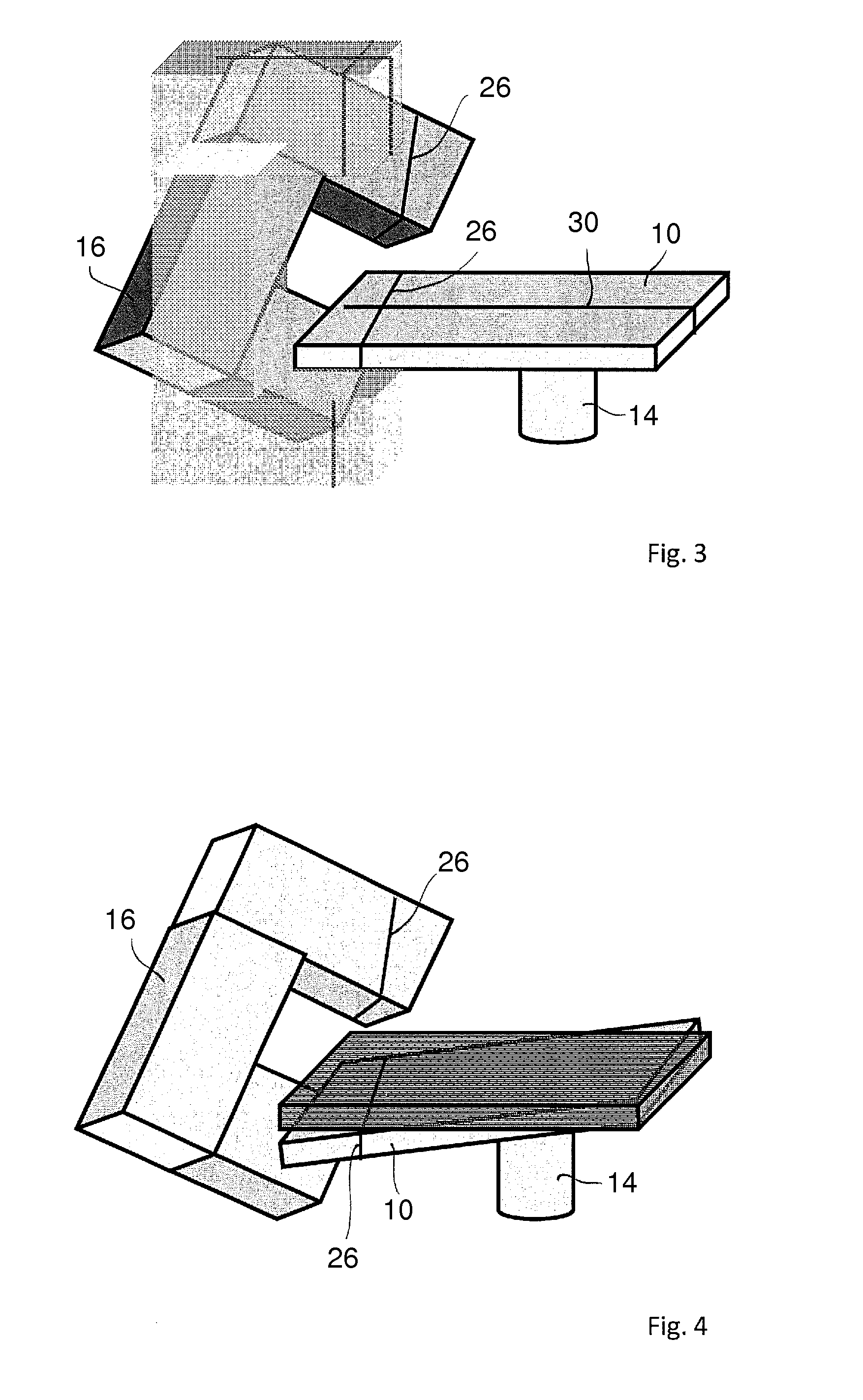
[0018]The system according to one implementation of the invention can comprise a radiation device and a patient table. A radiation device for cancer therapy of a patient is generally located in a radiation room. The radiation device may be a linear accelerator (LINAC), the head (gantry) of which rotates around the patient table supporting a patient during radiation treatment. According to this implementation, it is suggested that the above-explained room lasers permanently arranged in the radiation room for positioning a patient for radiation be used for further purposes, namely for the position determination of a patient and, if necessary, additional objects in the radiation room. Conventional laser triangulation may be used. At least one laser line, and preferably several laser lines, are at least projected at the patient and at least one laser line, and preferably all laser lines, are recorded by one or more high-resolution cameras. The system is thus structurally simplified thro...


PUM


Abstract

A system and method for determining the position of objects in a radiation room for radiation therapy comprises several room lasers arranged in the radiation room, each of which is designed for patient positioning to project at least one laser line onto the surface of a patient located on a patient table in the radiation room. At least one camera detects at least one laser line projected onto the surface of the patient by at least one of the room lasers, and an evaluation and control apparatus determines the coordinate points along the laser line projected onto the surface of patient during a radiation procedure based on measurement values detected by the camera through a real-time triangulation process and compares them with target coordinate points. The coordinate points determined during the radiation procedure may be saved for documentation of the radiation procedure.

Description

CROSS-REFERENCE TO RELATED APPLICATION[0001]This application claims priority to EP 13 196 634.3, filed Dec. 11, 2013, the content of which is incorporated herein in its entirety by reference.FIELD OF THE DISCLOSURE[0002]The disclosure relates to a system for determining the position of objects in a radiation room for radiation therapy and a corresponding method.BACKGROUND[0003]Radiation therapy of patients for cancer treatment takes place in radiation rooms. Tumors are thereby irradiated with ionizing radiation by means of radiation devices. The correct positioning of the patient is decisive so that the ionizing radiation hits the tumor optimally. In a computed tomography (CT) room that is separate from the radiation room, the area to be irradiated is localized based on CT images and markings are applied to the patient's body, based on which the patient is then positioned in the radiation room. For this, so-called room lasers are arranged in the radiation room. Room lasers are laser...

Claims


Application Information

Patent Timeline
Patent Type & Authority Patents(United States)
IPC IPC(8): G01B11/00A61N5/10A61B6/03A61B6/08A61B6/04
CPCG01B11/005A61B6/032A61B6/0492A61B6/08A61N5/1049A61N2005/105A61N2005/1059
Inventor HOFMANN, KARSTENKINDLEIN, JOHANN
Owner HOFMANN KARSTEN
Why Eureka
Try Eureka