

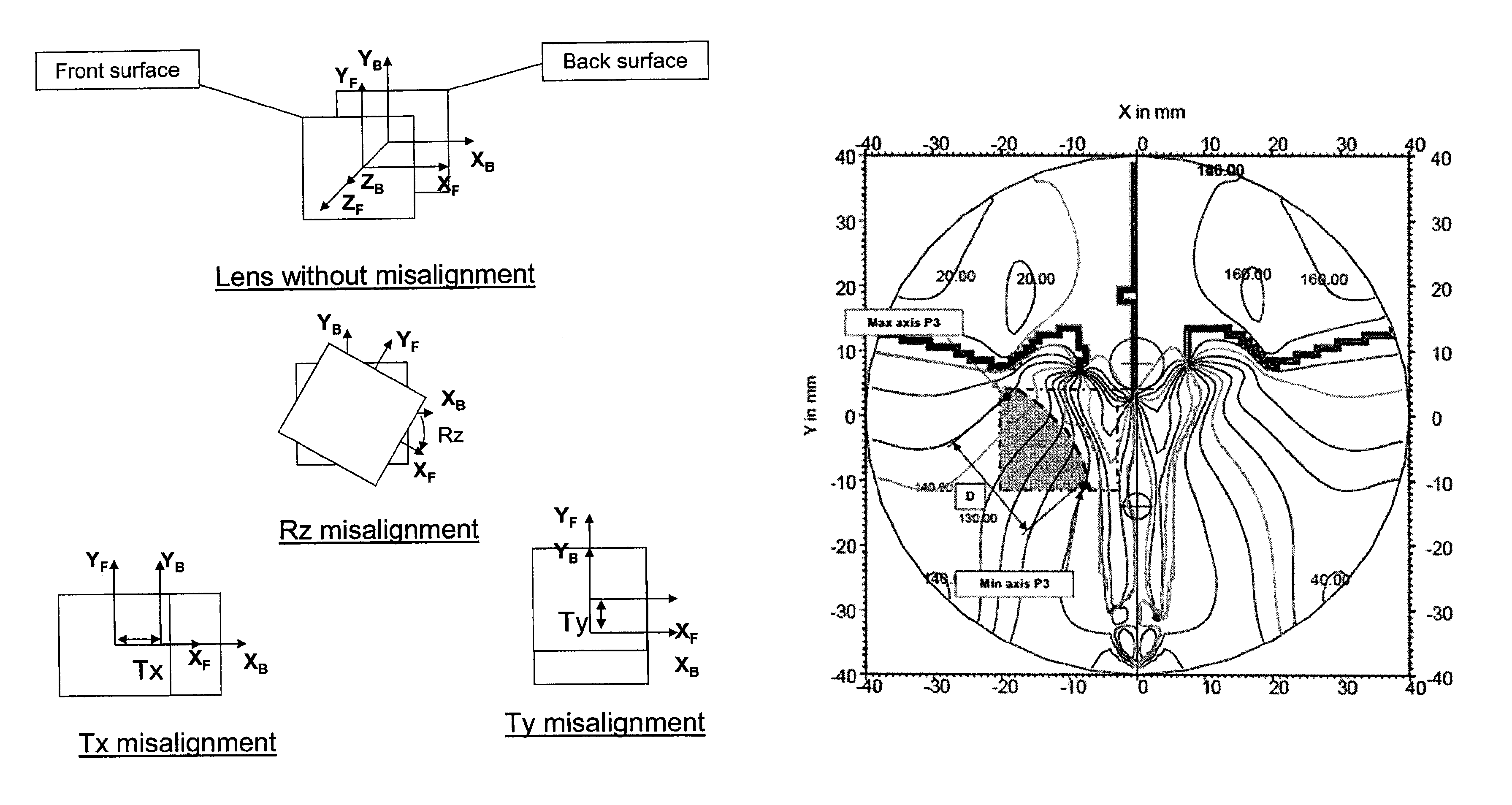
Methods for determining a progressive ophthalmic lens
a technology of progressive ophthalmology and lens, which is applied in the direction of spectacles/goggles, instruments, spectacles/goggles, etc., can solve the problems of affecting the optical quality of the image, causing optical defects that must be minimized, and different power correction values
- Summary
- Abstract
- Description
- Claims
- Application Information
AI Technical Summary
Benefits of technology
Problems solved by technology
Method used
Image

Examples
third embodiment
[0280]The chart in FIG. 31 provides illustrative values for the above-mentioned parameters related to the third embodiment shown in FIGS. 41 to 44.
[0281]The chart in FIG. 32 provides illustrative values for the above-mentioned parameters related to the first and second embodiments shown in FIGS. 33 to 40.
[0282]The method further comprises a step 20 of modifying the second aspherical surface so as to reach the target optical function for the lens and guarantee an optimum sharpness for the lens. The modifying of the second surface is carried out by optical optimization for minimizing the difference between a current optical function and the target optical function with a cost function. A cost function is a mathematical quantity expressing the distance between two optical functions. It can be expressed in different ways according to the optical criteria favored in the optimization. In the sense of the invention, “carrying out an optimization” should preferably be understood as “minimiz...
first embodiment
[0329]FIGS. 33 to 36 depict a first surface of a lens obtained in accordance with the invention.
second embodiment
[0330]FIGS. 37 to 40 depict a first surface of a lens obtained in accordance with the invention.
[0331]FIGS. 41 to 44 depict a first surface of a lens obtained in accordance with a third embodiment of the invention. It is noted that FIGS. 29 and 30 correspond to FIGS. 43 and 44, respectively.
PUM
 Abstract
Description
Claims
Application Information