Continuous ignition systems

a technology of continuous ignition and ignition system, which is applied in the direction of burner ignition device, machine/engine, lighting and heating apparatus, etc., can solve the problems of typical igniter failure, inability to provide an adequate spark for engine ignition, and more difficult ignition

Active Publication Date: 2017-02-14
COLLINS ENGINE NOZZLES INC
View PDF8 Cites 21 Cited by
  • Summary
  • Abstract
  • Description
  • Claims
  • Application Information

AI Technical Summary

Problems solved by technology

This increased concentration of fuel can wet the igniter, making it more difficult to light and can lead to carbon formations which will also make ignition more difficult.
Typical igniters can fail instantaneously and without warning, which also requires special design considerations in anticipation of failure.
The high voltages that are used to generate the spark can often find alternate paths in the circuit leading to the spark surface across which they can discharge and in such cases, the igniters can fail to provide an adequate spark for engine ignition.
The high voltage transformers required to generate the arc are heavy and require heavy electrical cables and connectors.
The sparks have trouble generating enough heat to vaporize cold fuel in cold conditions.
The ignition process can interfere with electronic device functions through stray electromagnetic interference (EMI).
Sparking systems have difficulty in maintaining a lit combustor under very low power or other unstable or transient mode of operation.
Leaving the spark plugs on for the entire mission can lead to early igniter deterioration and failure.

Method used


Image

  • Continuous ignition systems
  • Continuous ignition systems
  • Continuous ignition systems

Examples


Embodiment Construction

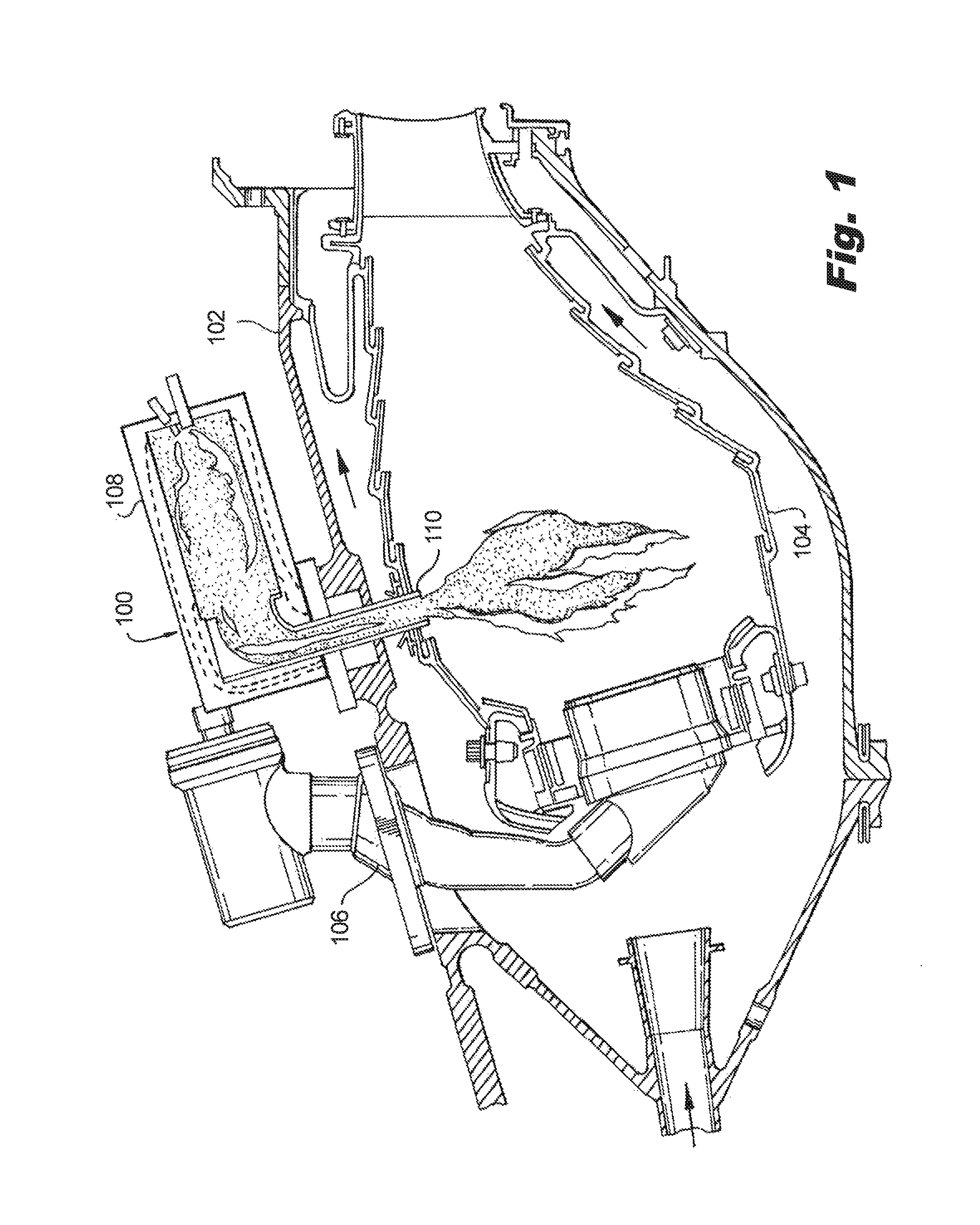
[0036]Reference will now be made to the drawings wherein like reference numerals identify similar structural features or aspects of the subject invention. For purposes of explanation and illustration, and not limitation, a partial view of an exemplary embodiment of an ignition system is shown in FIG. 1 and is designated generally by reference character 100. Other embodiments of ignition systems, or aspects thereof, are provided in FIGS. 2-24, as will be described. The systems and methods of the invention can be used, for example, to employ liquid fuel injection to improve the ignition performance of gas turbine engines. The systems and methods can be used in new engines, as well as to retrofit to existing engines to replace traditional ignition systems, for example.

[0037]In FIG. 1, ignition system 100 is shown mounted to a high-pressure casing 102 outboard of a combustor 104 of a gas turbine engine. Compressor discharge air enters the high-pressure casing on the left hand side of FI...


PUM


Abstract

A head assembly for an ignition system includes a head block and a plurality of igniters seated in the head block. The head block has an issue aperture and defines an issue axis, and is configured and adapted for sealably coupling with an igniter combustion chamber. The igniters are arranged about the issue aperture and include respective ignition members arranged obliquely with respect to the issue axis for igniting fuel exiting the issue aperture irrespective to orientation of the ignition system.

Description

CROSS-REFERENCE TO RELATED APPLICATIONS[0001]This application is a continuation-in-part of U.S. patent application Ser. No. 13 / 917,053 filed Jun. 13, 2013, and claims priority to U.S. Provisional Patent Application No. 61 / 900,644 filed on Nov. 6, 2013, both of which are incorporated by reference herein in their entireties.BACKGROUND OF THE INVENTION[0002]1. Field of the Invention[0003]The present invention relates to combustion, and more particularly to ignition systems such as in gas turbine engines.[0004]2. Description of Related Art[0005]A variety of devices are known for initiating combustion, for example in a gas turbine engine. Many gas turbine engines use spark igniters for ignition. One or more spark igniters are positioned to ignite a fuel and air mixture to initiate the flame in the combustor. These typical igniters provide ignition energy intermittently, and the spark event must coincide with a flammable mixture local to the igniter in order for engine ignition to occur. ...

Claims


Application Information

Patent Timeline
Patent Type & Authority Patents(United States)
IPC IPC(8): F02C7/266
CPCF02C7/266F05D2240/40F05D2250/314F23C2900/03005F23D2207/00
Inventor PROCIW, LEV A.RYON, JASON A.MYERS, STEVEN J.
Owner COLLINS ENGINE NOZZLES INC
Why Eureka
Try Eureka