Electrical energy store

a technology of energy storage and energy storage cells, applied in the direction of fuel and secondary cells, etc., can solve the problems of high complexity of cell parts, high material choice of cell materials, and deterioration of individual components, and achieve the effect of sufficient freedom of movement of shuttle gas

Active Publication Date: 2017-02-28
SIEMENS ENERGY GLOBAL GMBH & CO KG
View PDF12 Cites 0 Cited by
  • Summary
  • Abstract
  • Description
  • Claims
  • Application Information

AI Technical Summary

Benefits of technology

[0007]This gas duct has a plurality of advantageous effects. Since a shuttle gas, which, in particular, contains hydrogen and water and which is dealt with in more detail hereafter, can freely flow and diffuse in this gas duct, the result of this is that all regions, even regions in the middle of the duct, are always supplied homogenously with the shuttle gas which, for example, is necessary for initial reduction. A homogenous supply of the storage medium over the entire duct length ensures optimum utilization of the entire storage capacity of the energy storage cell and therefore of the electrical energy store. This leads, in turn, to a constant energy absorption capacity of the energy store and, last but not least, to a longer service life. Furthermore, by means of these gas ducts, a lack of shuttle gas, which may be due, for example, to a leak of the overall energy store, can be compensated. Furthermore, when the energy store is being put into operation or during maintenance work upon it, an appropriate reaction gas, such as, for example, pure hydrogen, can be introduced from outside, in order to achieve an overall reduction of the storage medium which is advantageous when the store is deactivated.
[0008]It became apparent that it was appropriate if the storage medium is arranged at a distance from the storage electrode so that the gas duct is located between the storage electrode and the storage medium.
[0009]For this purpose, it is expedient, in turn, to provide a fixing device which fixes the storage medium to the duct walls. A fixing device is understood, in principle, to mean any fixing means which enables the storage medium to be arranged in the ducts such that a distance from the storage electrode or the duct walls can be ensured. This may, in particular, also be a clamping device, for example an undercut in the ducts or mechanical fastening.
[0010]It became apparent that it was appropriate to configure the fixing device in the form of a net, in particular of a metallic net. This metallic net, in turn, may be nickel-based. The net in this case runs essentially parallel to the storage electrode in the ducts. In this case, it is advantageously fastened to two duct walls running parallel to one another.
[0011]The fastening of the net to the duct walls may take place, for example, by means of a spot welding method, but it may also be fastened to a frame which, in turn, has two frame flanks which run parallel to the duct walls and between which the net is fastened.
[0012]The cross-sectional area of the ducts may be at least 5% larger than the cross-sectional area of the storage medium. This, in turn, means that the gas ducts have a cross-sectional area which amounts to at least 5% of the cross-sectional area of the storage medium. This duct cross section of at least 5% of the storage medium has proved to be expedient in order to ensure sufficient freedom of movement of the shuttle gas along the gas duct.

Problems solved by technology

On account of the high temperatures required for this process, the choice of material for the cell materials used and the design of the cell parts and also the arrangement of the storage medium are highly complex.
In particular, the individual components deteriorate after a plurality of redox cycles which are operated at said operating temperatures.

Method used


Image

  • Electrical energy store
  • Electrical energy store
  • Electrical energy store

Examples


Embodiment Construction

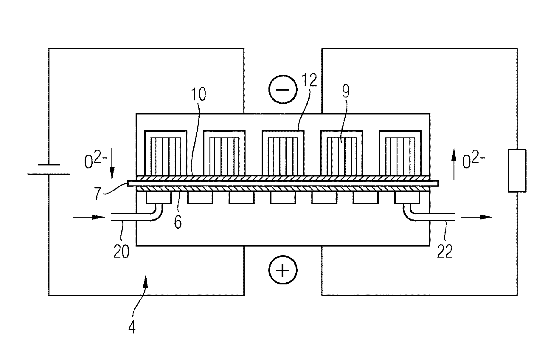
[0022]The working of a rechargeable oxide battery (ROB) will first be described diagrammatically by means of FIG. 1, in as much as is necessary for the present description of the invention. In a conventional set-up of an ROB, a process gas, in particular air, is injected via a gas supply 20 at a positive electrode 6 which is also designated as an air electrode, oxygen being extracted from the air. The oxygen passes in the form of oxygen ions O2− through a solid electrolyte 7, resting against the positive electrode, to a negative electrode 10 which is also designated as a storage electrode. If, then, a dense layer of the active storage material were present on the storage electrode at the negative electrode 10, the charging capacity of the battery would quickly be exhausted.

[0023]For this reason, it is expedient to use as energy storage medium at the negative electrode 10 a storage medium 9 composed of porous material which contains a functionally acting oxidizable material as an act...


PUM

PropertyMeasurementUnit
diameteraaaaaaaaaa
temperaturesaaaaaaaaaa

Abstract

An energy store is provided, having at least one stack, each stack having at least one storage cell, which in turn has an air electrode and a storage electrode. The storage electrode is adjacent to channels, which contain a storage medium and water vapor. The channels have a larger cross-sectional area than the cross-section of the storage medium, which condition causes unhindered spreading of a reaction gas in the area between the storage electrode and the storage medium.

Description

CROSS REFERENCE TO RELATED APPLICATIONS[0001]This application is the U.S. National Stage of International Application No. PCT / EP2013 / 068710 filed 10 Sep. 2013, and claims the benefit thereof. The International Application claims the benefit of German Application No. DE 102012217290.4 filed 25 Sep. 2012. All of the applications are incorporated by reference herein in their entirety.FIELD OF INVENTION[0002]The invention relates to an electrical energy store.BACKGROUND OF INVENTION[0003]For the storage of excess electrical current which occurs, for example, when current is being generated by means of renewable energy sources or by power stations operated in the optimum efficiency range and for which there is temporarily no demand in the network, various technical alternatives are adopted. One of these is the rechargeable oxide battery (ROB). ROBs are conventionally operated at temperatures of between 600° C. and 800° C. In this case, oxygen, which is supplied at an air electrode of the...

Claims


Application Information

Patent Timeline
Patent Type & Authority Patents(United States)
IPC IPC(8): H01M12/08
CPCH01M12/08Y02E60/10
Inventor DRENCKHAHN, WOLFGANGGREINER, HORSTKELLNER, NORBERTLANDES, HARALDREICHENBACHER, ROLAND
Owner SIEMENS ENERGY GLOBAL GMBH & CO KG
Why Eureka
Try Eureka