

Air mattresses having internal diagonal support structures
a technology of diagonal support structure and air mattress, which is applied in the field of inflatable mattresses to achieve the effect of increasing top-to-bottom rigidity, side and/or corner rigidity
- Summary
- Abstract
- Description
- Claims
- Application Information
AI Technical Summary
Benefits of technology
Problems solved by technology
Method used
Image

Examples
embodiment 300
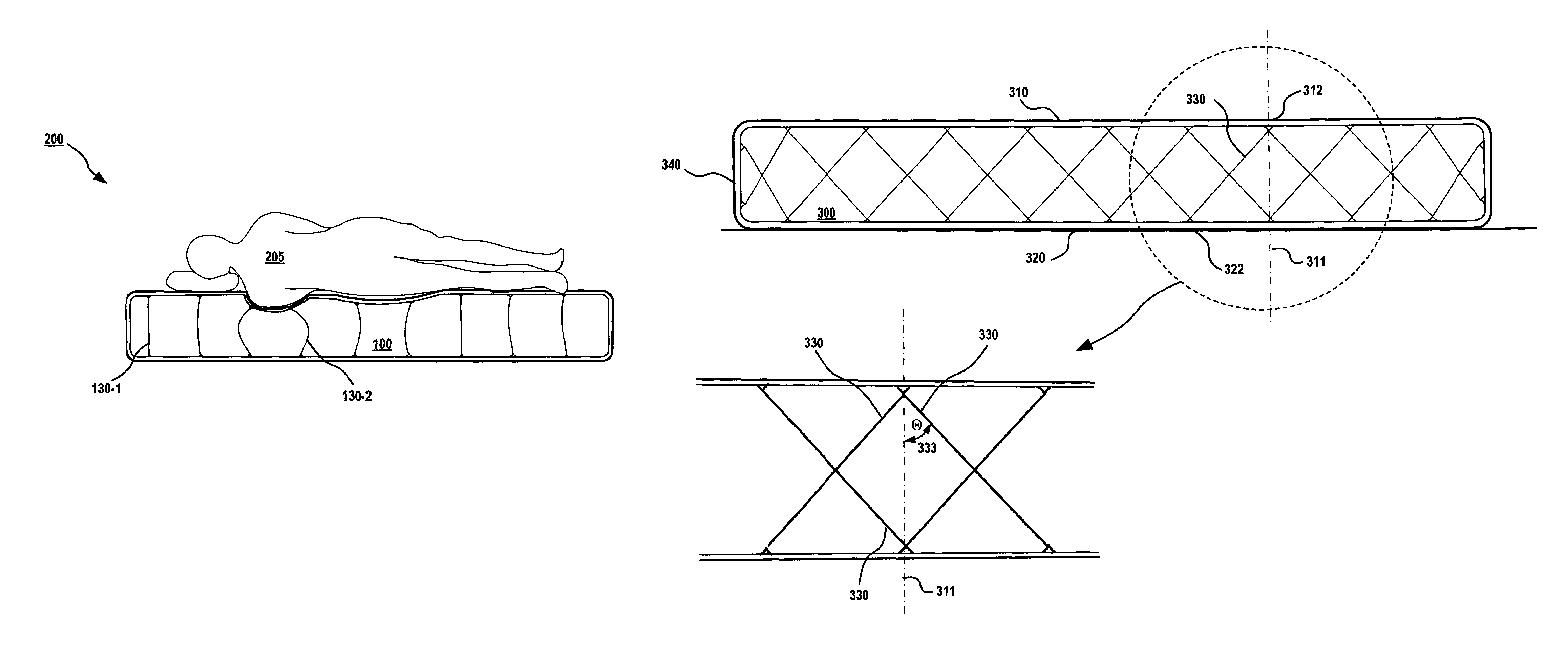
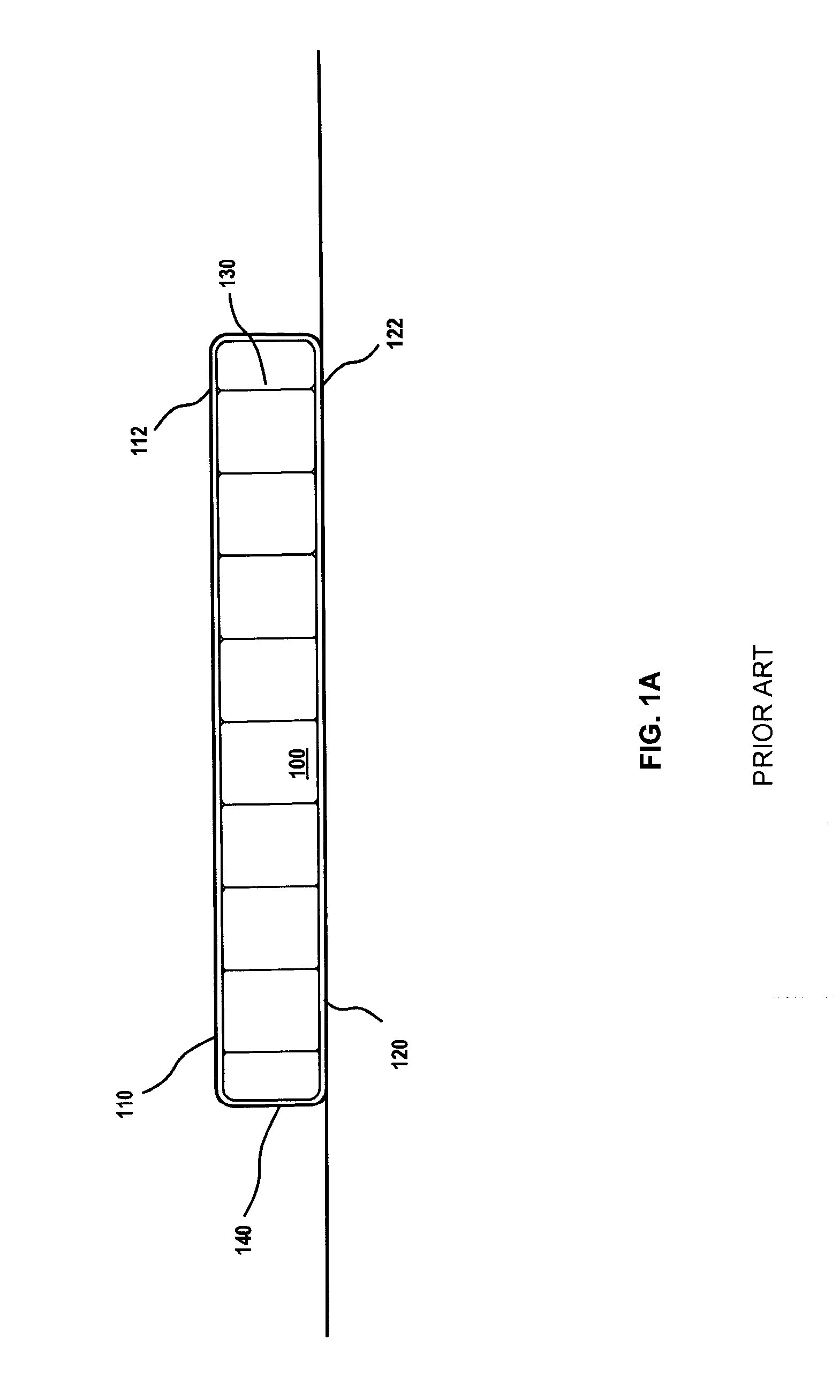
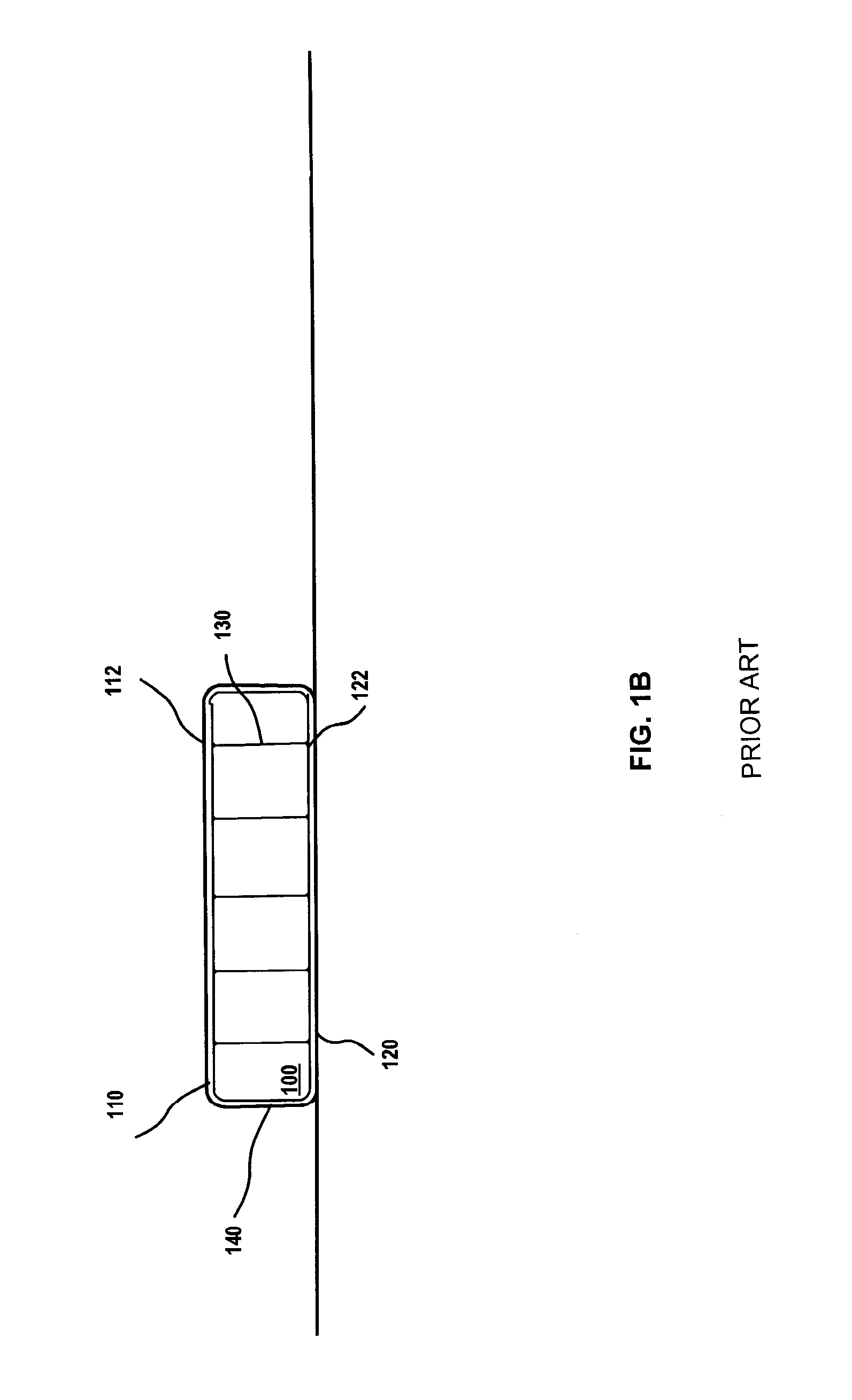
[0037]As used herein, a support element in a diagonal configuration refers to a support element that is oriented at an angle relative to a vertical elements of the structure when in normal use. A traditional vertical support element 130 is shown in FIG. 1, while diagonal support elements are illustrated in various embodiments from FIG. 3A through the end of this disclosure. For example, as shown in FIG. 3A in cross-section, an air mattress embodiment 300 is shown in cross-section as it would be placed on a level floor. A vertical axis 311 intersects top structure 310 (e.g., a PVC or other sheet material, etc.) and a bottom structure at approximately a 90 degree angle. A diagonal support element 330 is offset from the vertical by an angle Θ (Theta) as shown. As noted previously with respect to FIG. 1, traditional air mattresses use only vertical elements coupled between the top and bottom surfaces (e.g., along axis 311 as shown). In various embodiments, alternate and / or additional st...
embodiment 400
[0042]FIG. 4B illustrates embodiment 400 from a top view showing the internal support element configuration for diagonal support elements 430 and vertical support elements 435 (shown in FIG. 4B as a dot representing their orientation up / down relative to the top view shown.
[0043]FIG. 5 illustrates details of another embodiment 500 of an air mattress, in top view, in accordance in accordance with certain aspects. Embodiment 500 may be configured similarly to the other embodiments described elsewhere herein and may include, as shown, internal support elements 530 arrayed in vertical and / or horizontal orientations (as seen from the top) as shown. This configuration contrasts slightly from the configuration of embodiment 400 where the support elements 430 are arrayed in a diagonal arrangement (as seen from the top view) rather than in a horizontal / vertical grid as shown in FIG. 5.
embodiment 500
[0044]In embodiment 500, additional stabilization for corner 544, in the form of additional support elements 545, as shown in dashes, may optionally be included. In this configuration, one or more additional support elements may be coupled between various internal points and the corner 544 so as to provide additional cross-support to keep the side from collapsing under load and / or to provide more rigidity.
[0045]Vertical elements (as seen in a side view such as that of FIG. 4A as elements 435, may also be used and may be coupled to the top structure 510 at connection points 512 (and to corresponding points on a bottom structure (not shown). Structural support elements 530 may also be coupled between the air mattress top element 510 and bottom element, and the support elements may be, for example, rigid or flexible cords, cables, or other structures such as straps, inflatable elements, etc. The support elements may attach at internal connection points 512 and / or at side connection poi...
PUM
 Abstract
Description
Claims
Application Information