
Powered mobility device

a mobility device and power supply technology, applied in the direction of wheelchair/patient conveyance, transportation and packaging, cycles, etc., can solve the problems of not being able to be used easily or effectively on soft surfaces such as lawns or undulating surfaces, and most wheelchairs are not suitable for all surface types,

Active Publication Date: 2017-03-07
OGO TECH LTD
View PDF10 Cites 2 Cited by
  • Summary
  • Abstract
  • Description
  • Claims
  • Application Information

AI Technical Summary

Benefits of technology

The patent describes a device that helps users move around more easily. The device moves based on the user's weight displacement, which is controlled through a joystick. The joystick allows for finer control and steering of the device, making it easier to maneuver around. The device also adjusts its degree of turn based on the user's movement in the left or right direction, making the turns tighter and more precise. Overall, this technology makes it easier for people to use mobility devices and more confidently move around.

Problems solved by technology

A problem with existing mobility devices such as wheelchairs is that they are not easily operable by a user, especially those users that have significant loss or impaired movement of their limbs (arms and legs).
Also most wheelchairs are not suitable to be used on all surface types.
They are not able to be used easily or effectively on soft surfaces such as lawns or undulating surfaces, i.e. they are not able to be used “off road”.
They are prone to get stuck and require assistance of others to be able to go “off road”.
It is known to have wheel chairs that are controlled by the weight placement of the user, however these are not suitable for providing fine control of such movement in places where required (such as a crowded place or in a shop) or are not suitable for “off road” use.

Method used


Image

  • Powered mobility device
  • Powered mobility device
  • Powered mobility device

Examples


Embodiment Construction

)

[0059]The following description will describe the invention in relation to preferred embodiments of the invention, namely a powered mobility device, typically a powered wheelchair, that is able to be steered with or without the use of hands The invention is in no way limited to these preferred embodiments as they are purely to exemplify the invention only and that possible variations and modifications would be readily apparent without departing from the scope of the invention.

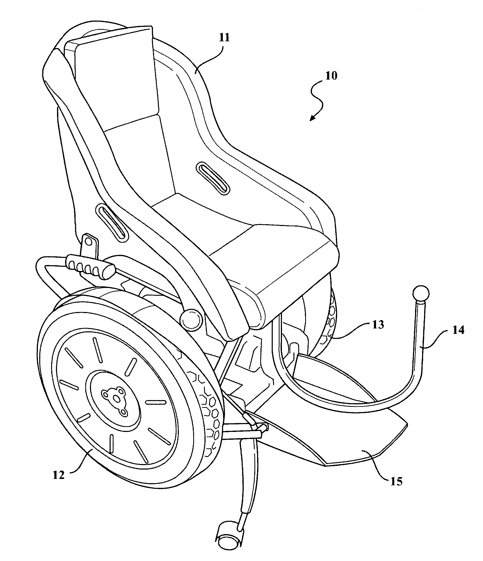
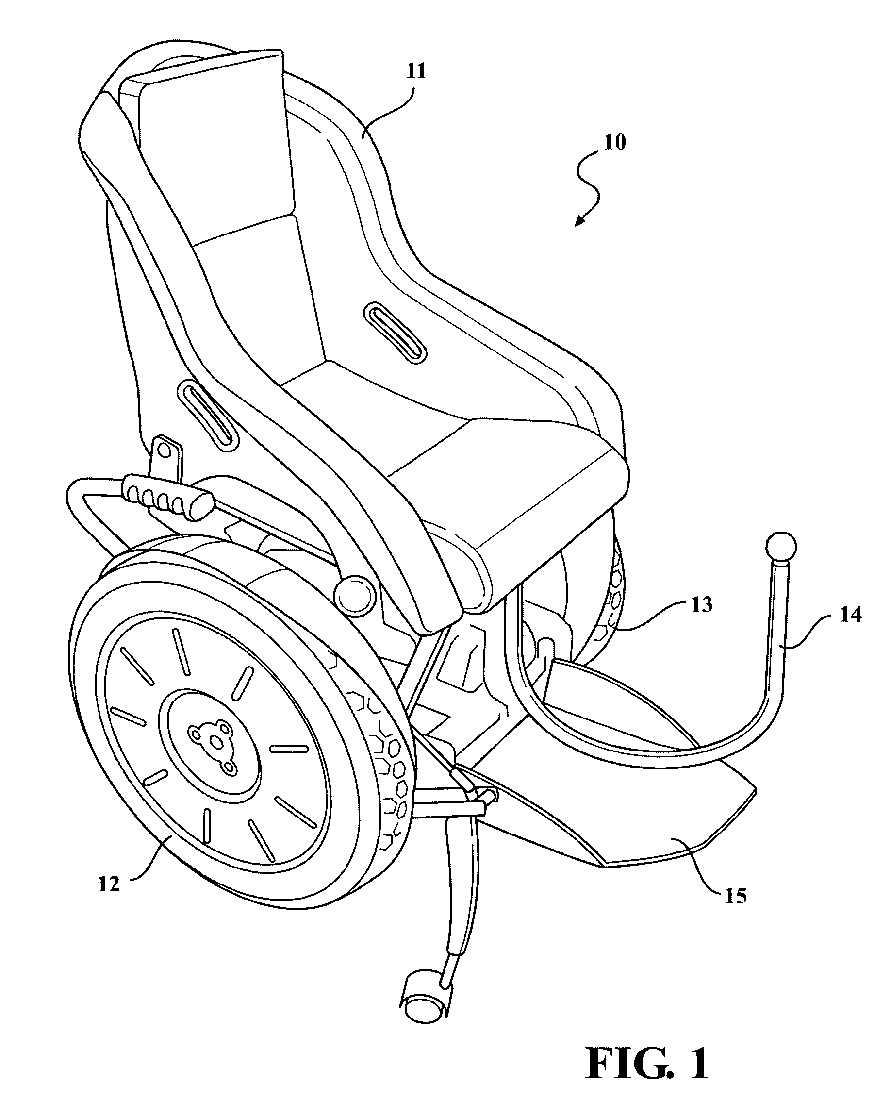
[0060]The mobility device shown in the figures is to a preferred, but not limiting, embodiment of a wheelchair 10.

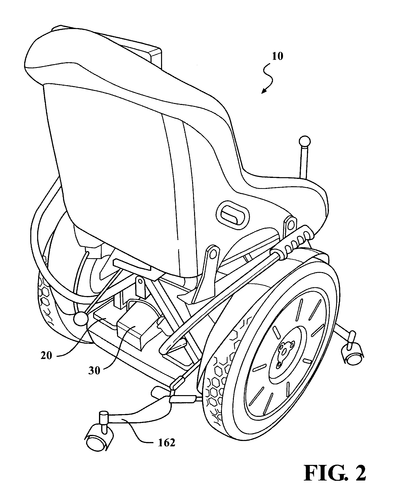
[0061]FIGS. 1 to 4 show differing views of the wheelchair 10 and FIGS. 5 & 6 show the wheelchair 10 with the seat 11 removed.

[0062]The wheelchair 10 is a powered wheelchair 10 and is typically powered by electric battery, however other known modes of powering the wheelchair 10 are envisaged.

[0063]The wheelchair 10 is able to be driven on road and off-road. The wheelchair 10 is able to be manoeuvred...


PUM


Abstract

A mobility device includes at least two drive wheels mounted on a shaft; a drive controller drivingly coupled to the shaft; a seat mounted to a tilt mechanism such that the seat is able to tilt in a forward, backward, left and right directions as a result of the user shifting their body weight in either of those directions; a weight displacement sensor connectable to the tilt mechanism and the drive controller such that upon sensing a weight displacement of a user in a particular direction the weight displacement sensor causes the drive controller to impart drive to the drive wheels to move the mobility device in the direction of the sensed displaced weight of the user so that the mobility device is able to be driven in a forward and backward direction and steered in a left or right direction.

Description

FIELD OF THE INVENTION[0001]The invention relates to a Powered Mobility Device, typically a powered wheelchair, that is able to be steered with or without the use of handsBACKGROUND OF INVENTION[0002]A problem with existing mobility devices such as wheelchairs is that they are not easily operable by a user, especially those users that have significant loss or impaired movement of their limbs (arms and legs).[0003]Also most wheelchairs are not suitable to be used on all surface types. They are not able to be used easily or effectively on soft surfaces such as lawns or undulating surfaces, i.e. they are not able to be used “off road”. They are prone to get stuck and require assistance of others to be able to go “off road”.[0004]Powered wheelchairs typically require hand controls to steer and propel the wheel chair forward and backward. It is known to have wheel chairs that are controlled by the weight placement of the user, however these are not suitable for providing fine control of ...

Claims


Application Information

Patent Timeline
Patent Type & Authority Patents(United States)
IPC IPC(8): A61G5/04B62K3/00A61G5/10
CPCA61G5/041A61G5/043B62K11/007A61G2203/14A61G2203/36A61G2203/42A61G2203/44A61G5/1051A61G5/1089
Inventor HALSALL, KEVIN THOMAS
Owner OGO TECH LTD
Learn More