Exoskeleton mechanism for joint movement assistance

a technology of exoskeleton and joint movement, which is applied in the field of exoskeleton mechanism, can solve the problems of large volume of exoskeleton mechanism, and disturbance of patient movement, and achieve the effect of stably supporting

Active Publication Date: 2017-03-14
KOREA INST OF SCI & TECH
View PDF11 Cites 7 Cited by
  • Summary
  • Abstract
  • Description
  • Claims
  • Application Information

AI Technical Summary

Benefits of technology

[0010]The present disclosure is directed to provide an exoskeleton mechanism, which may be conveniently worn by a wearer and also be easily taken off.
[0033]As described above, in the exoskeleton mechanism according to the present disclosure, driving motors are mounted to bottom surfaces of a fixed frame and a rotatable frame, and the rotary shafts of the driving motors are positioned in the length direction of the fixed frame or the rotatable frame. In other words, since no motor protrudes to the side of the exoskeleton mechanism, the entire configuration of the exoskeleton mechanism may be configured with a dense design, and the exoskeleton mechanism does not disturb the movement of a wearer.
[0034]In addition, since the exoskeleton mechanism according to the present disclosure is configured so that the limb may be placed on the fixed frame, the rotatable frame and a support frame, the wearer may rapidly move the limb out of the exoskeleton mechanism at emergency.
[0036]Further, in the exoskeleton mechanism according to the present disclosure, since links and fixed brackets are positioned at both sides of the fixed frame, the upper arm may be stably supported. Therefore, when a wearer moves the arm by using the exoskeleton mechanism, it is possible to prevent the arm from falling out of the fixed frame.

Problems solved by technology

In addition, due to the use of the ring-type guide rail, the exoskeleton mechanism has a great volume, which may frequently disturb the movement of the patient.
Moreover, since a motor for connecting links is formed to protrude to the side of the frame, the exoskeleton mechanism has a great volume, and designing the exoskeleton mechanism is difficult.

Method used


Image

  • Exoskeleton mechanism for joint movement assistance
  • Exoskeleton mechanism for joint movement assistance
  • Exoskeleton mechanism for joint movement assistance

Examples


Embodiment Construction

[0046]Hereinafter, an exemplary embodiment of an exoskeleton mechanism according to the present disclosure will be described in detail with reference to the accompanying drawings.

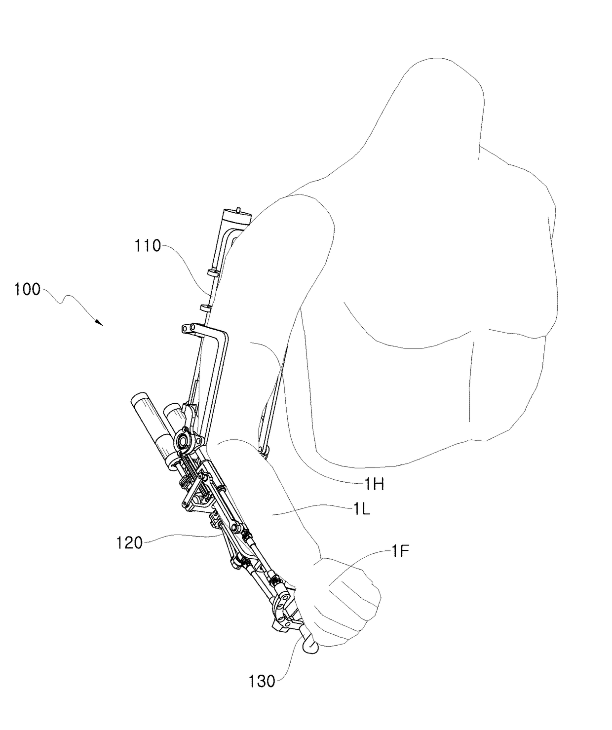
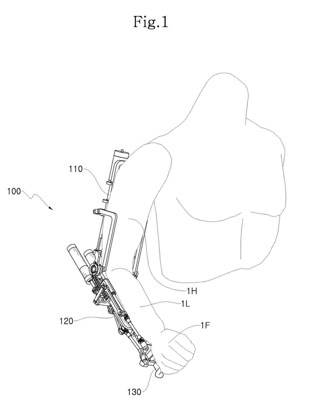
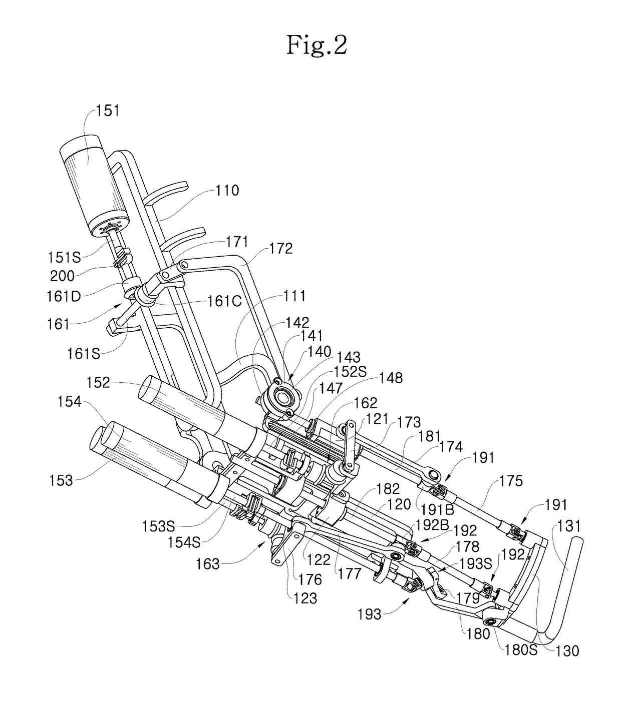
[0047]FIG. 1 is a perspective view showing an exoskeleton mechanism worn by a user according to an embodiment of the present disclosure, FIG. 2 is a perspective view showing the exoskeleton mechanism of FIG. 1, observed at a different angle, FIGS. 3 to 5 are perspective view for illustrating operations of a first driving motor of the exoskeleton mechanism, FIGS. 6 to 8 are perspective view for illustrating operations of a second driving motor of the rotatable frame of the exoskeleton mechanism, FIGS. 9 to 11 are perspective view for illustrating operations of a first driving motor of the rotatable frame of the exoskeleton mechanism, FIGS. 12 to 14 are perspective view for illustrating operations of a third driving motor of the rotatable frame of the exoskeleton mechanism, FIG. 15 is a diagram showing an ope...


PUM


Abstract

An exoskeleton mechanism according to the present disclosure includes: a fixed frame positioned to correspond to an upper physique; a rotatable frame positioned to correspond to a lower physique and coupled to the fixed frame by a hinge unit to be rotatable in the vertical direction; a support frame for supporting a terminal; a first motor mounted to the fixed frame and connected to the rotatable frame to drive the rotatable frame to rotate in the vertical direction; motors mounted to the rotatable frame and connected to the support frame to drive the support frame to rotate in the vertical direction and in the horizontal direction and rotate around an axis (roll axis) of the lower physique; links for connecting the first motor and the rotatable frame; and links for connecting the motors and the support frame.

Description

CROSS-REFERENCE TO RELATED APPLICATION[0001]This application claims priority to Korean Patent Application No. 10-2011-0101430, filed on Oct. 5, 2011, and all the benefits accruing therefrom under 35 U.S.C. §119, the contents of which in its entirety are herein incorporated by reference.BACKGROUND[0002]1. Field[0003]The present disclosure relates to an exoskeleton mechanism, and more particularly, to an exoskeleton mechanism for assisting joint movement of a human or a robot (a “wearer”).[0004]2. Description of the Related Art[0005]An exoskeleton mechanism is mounted to an arm or leg of a patient, who feels inconvenience in the limb, to assist in or reinforce the muscular power of the patient or mounted to a robot so that a joint of the robot generates a force over a designed torque.[0006]The exoskeleton mechanism is configured so that a frame corresponding to a physique of the limb (hereinafter, generally referred to as an “arm”) of the wearer allows the muscle of the arm to smoothl...

Claims


Application Information

Patent Timeline
Patent Type & Authority Patents(United States)
IPC IPC(8): A61H1/02B25J9/00
CPCA61H1/0277B25J9/0006B25J9/0072A61H2201/1215A61H2201/149A61H2201/165A61H2201/5007A61H2201/5061A61F2/70A63B21/005A63B21/065
Inventor HONG, MANBOKKIM, KEEHOON
Owner KOREA INST OF SCI & TECH
Why Eureka
Try Eureka