Eureka AIR delivers breakthrough ideas for toughest innovation challenges, trusted by R&D personnel around the world.

Control of telecommunications system

Active Publication Date: 2017-03-28
BRITISH TELECOMM PLC
View PDF12 Cites 0 Cited by
  • Summary
  • Abstract
  • Description
  • Claims
  • Application Information

AI Technical Summary

Benefits of technology

This patent is about controlling telecommunications systems in call centers and trading rooms. The invention aims to measure the performance of these systems in delivering call event notifications across various network architectures and predict their future performance. The notification of incoming call alerts to all terminals must occur in a way that maintains a democracy of service and prevents delay. The invention discusses several factors that affect the fairness of call event notification delivery, such as the software architecture of the central call control server, network topology, network latency, and more. The patent also mentions the use of a multicast protocol for efficient delivery of notifications, but notes that it complicates network design and makes providing a resilient solution more difficult. The invention proposes a Call Distribution Module for a small number of terminals, but notes that it helps to maintain a democracy of service and prevent delay only when there are a small number of terminals attached to each module.

Problems solved by technology

The overall performance of the system will be limited by the characteristics of the underlying network.
However, in the latter case, it is not possible to arrange for call alerts to be perfectly synchronised, because a typical digital processor performs operations in a sequence of steps, rather than strictly simultaneously.
In very active or competitive environments this puts those who are not alerted to an incoming call first at a disadvantage, as they will have less opportunity to answer the call.
However, the number of threads that can be assigned to this task are limited by system resources and the maximum throughput of messages onto the network.
However, multicast protocols complicate the network design and make providing a resilient solution more difficult, especially if the scope of delivery is expected to extend to a WAN (wide area network) deployment.
However, again this approach is not appropriate for all network architectures, and in particular there may be difficulties in allocating individual terminals to their appropriate call distribution modules in a dynamic environment as users' requirements change.

Method used


Image

  • Control of telecommunications system
  • Control of telecommunications system
  • Control of telecommunications system

Examples


Embodiment Construction

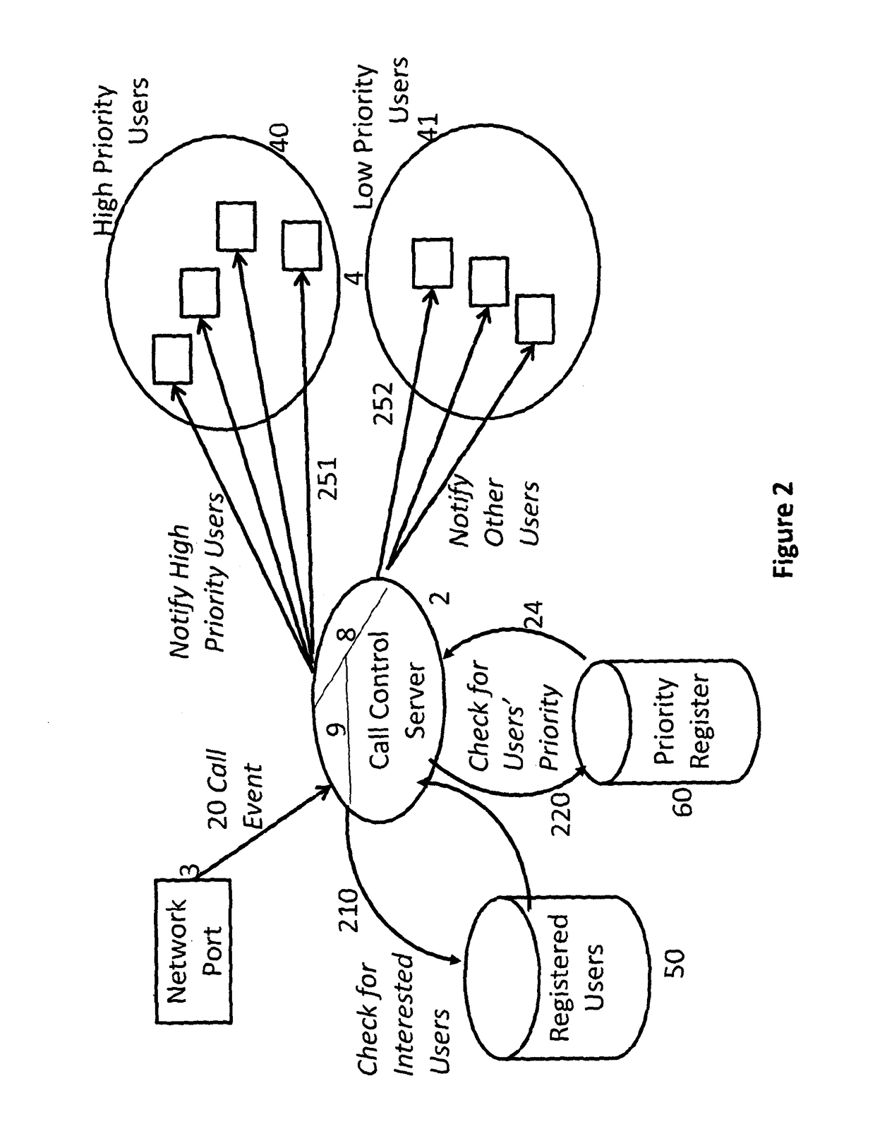
[0024]Some variants of the selection process are illustrated in the Figures.

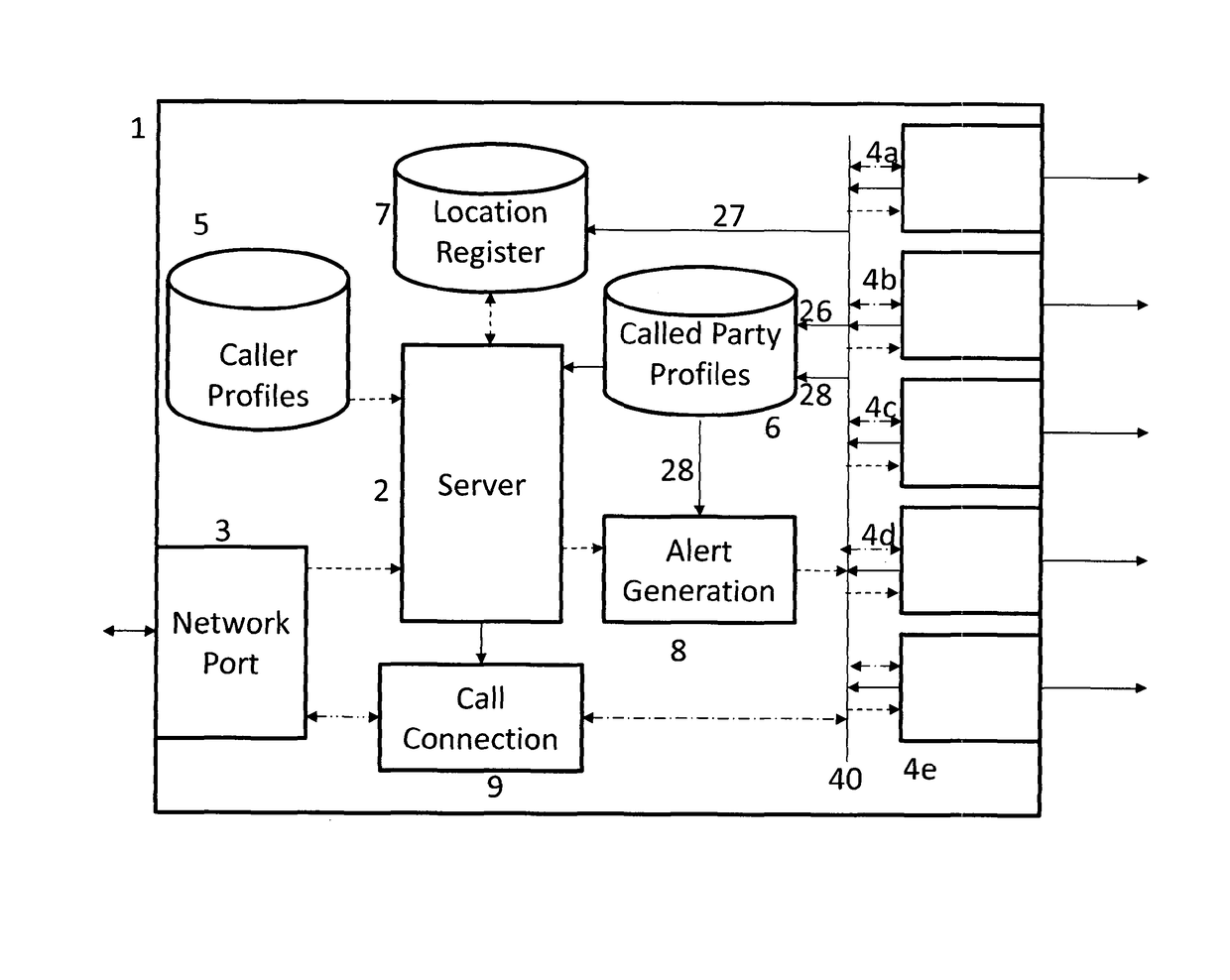
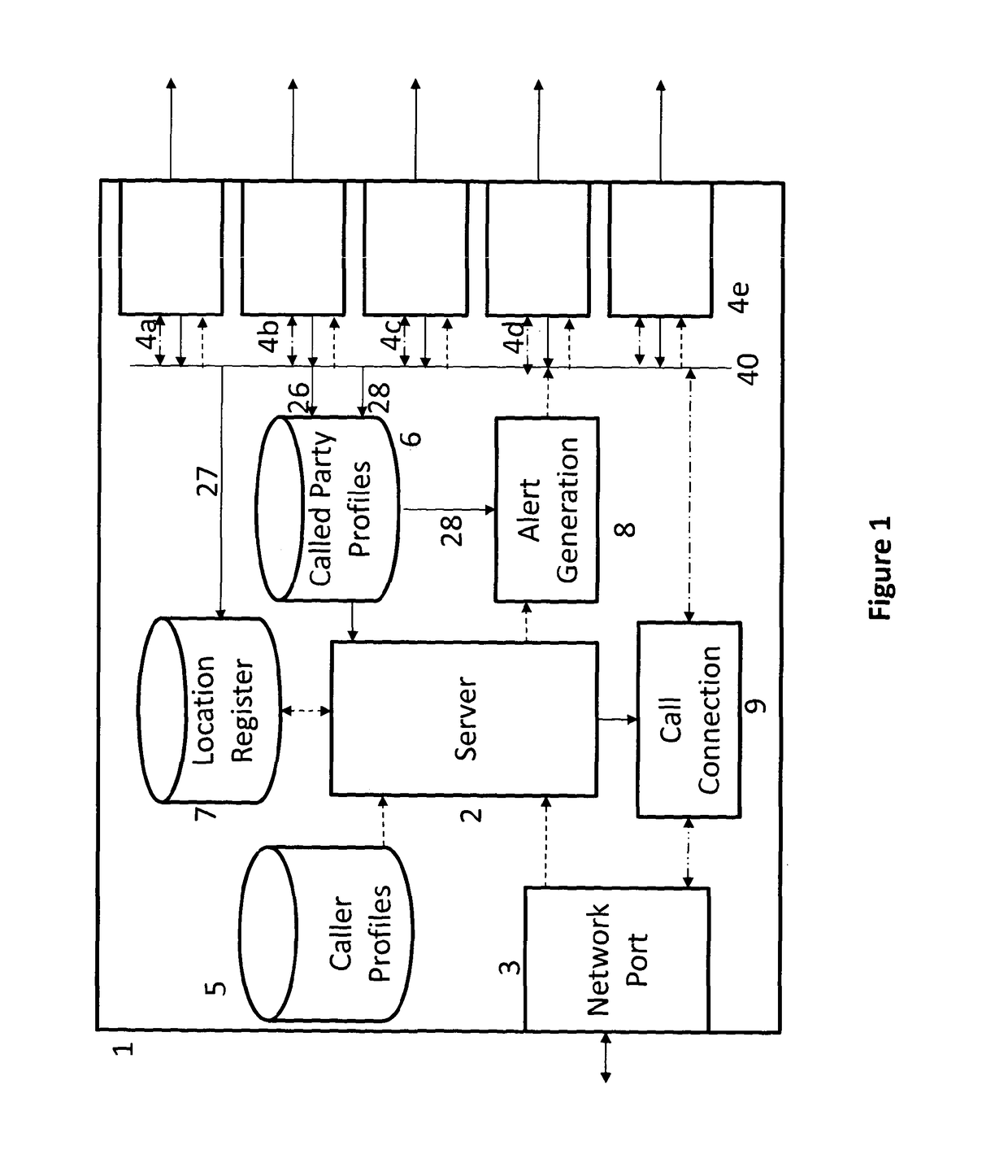
[0025]In this embodiment the invention is implemented in a software component, and specifically by suitable programming of a call control server 2.

[0026]FIGS. 1 and 2 depict an installation 1 having a server 2, an external port 3 for connection to a network and a plurality of local ports 4a, 4b, etc for connection to individual user terminals. The various components communicate with each other through a databus 40, although for clarity some functional connections to the server 2 are depicted separately.

[0027]Associated with the server 2 are data storage media 5, 6, 7, (50, 60). A first data storage medium 5 stores data relating to individual parties which may attempt to make an incoming call through the network port 3. Such data may include a calling line identity (CLI) call, data relating to previous calls made by that user, for example the user or user terminal that answered a previous call, or a flag set ...


PUM


Abstract

A telecommunications server (2) controlling a plurality of telecommunications terminals (4) connected to a packet switched telecommunications system (40, 41), responds to call events (20) by transmitting an alert (251, 252) to each of the terminals. If the server is not capable of processing all the required event alerts in parallel, it processes the event alerts to the terminals in a predetermined sequence, according to stored prioritization rules (60). The priority accorded to an individual terminal may be set according to the alert mode (visual-only, or audible) currently set for that terminal (or the user currently using the terminal) for that call type or calling party.

Description

[0001]This application is the U.S. national phase of International Application No. PCT / GB2012 / 000394, filed 27 Apr. 2012, which designated the U.S. and claims priority to EP Application No. 11250605.0, filed 23 Jun. 2011, the entire contents of each of which are hereby incorporated by reference.BACKGROUND AND SUMMARY[0002]This invention relates to the control of telecommunications systems, and in particular of IP-based local networks for use in call centres, trading rooms and other applications. In systems designed for use in trading rooms of the trading financial services industry, it is common practice to provide a telecommunications terminal or “turret” for each user. Such networks provide a call server which handles incoming and outgoing call requests, and routes calls to the turrets appropriately.[0003]Individual terminals are notified of changes of state of a Trunk or DDI (direct dial in telephone extension) in response to many kinds of call events, such as users going “on-hoo...

Claims


Application Information

Patent Timeline
IPC IPC(8): H04M3/46H04M3/523H04M3/436
CPCH04M3/465H04M3/46H04M3/436H04M3/5232
Inventor PRITCHARD, SIMON JEREMYBEAUCHAMP, RICHARD ANDREWVADGAMA, SANJAY RUGNATH
Owner BRITISH TELECOMM PLC
Why Eureka
Eureka Blog
Learn More