Carrying case for a wig

a wig and carrier technology, applied in the field of luggage devices, can solve the problems of unusable wig carriers, unwieldy carrying cases, and difficult use of current wig carriers, and achieve the effect of less space and closer access

Inactive Publication Date: 2017-04-04
ROSENBLATT ELI
View PDF21 Cites 3 Cited by
  • Summary
  • Abstract
  • Description
  • Claims
  • Application Information

AI Technical Summary

Benefits of technology

[0004]The wig carrying case described herein is an elongated carrying case made of two segments that are joined by a hinge that runs parallel to the longitudinal axis of the carrier. The two segments, when brought together, form a housing to enclose a wig. A first segment has a floor surface that extends in a lateral direction past its roof surface. An upwardly projecting cylindrical bar is mounted to the floor surface of the first segment and which serves to anchor a wig head. Because the floor surface upon which the cylindrical bar is positioned extends past the roof section, a user may place a wig head directly in a downward motion onto the bar—without having to laterally slide the wig head into the case. Moreover, because the carrier opens along its longitudinal axis—a user has closer access to the inside of the carrier. In addition, the inventive wig carrier occupies less space than wig carrier having a front opening door, and as such, it may be opened in more confined spaces, such as in a crowded dressing room or in an automobile.

Problems solved by technology

Wigs are delicate items and they must be handled carefully in transport.
The carrying cases for wigs currently available on the market are unwieldy and they not user friendly.
In addition, current wig carriers do not allow for the wig head to be secured within the carrier.
These and other factors make current wig cases difficult to use and there is a need in the art for an improved wig carrier case.

Method used


Image

  • Carrying case for a wig
  • Carrying case for a wig
  • Carrying case for a wig

Examples


Embodiment Construction

[0013]Embodiments of the present invention will now be described with reference to the above-identified Drawings. However, the Drawings and the description herein of the invention are not intended to limit the scope of the invention. It will be understood that various modifications of the present description of the invention are possible without departing from the spirit of the invention. Also, features described herein may be omitted, additional features may be included, and / or features described herein may be combined in a manner different from the specific combinations recited herein, all without departing from the spirit of the invention.

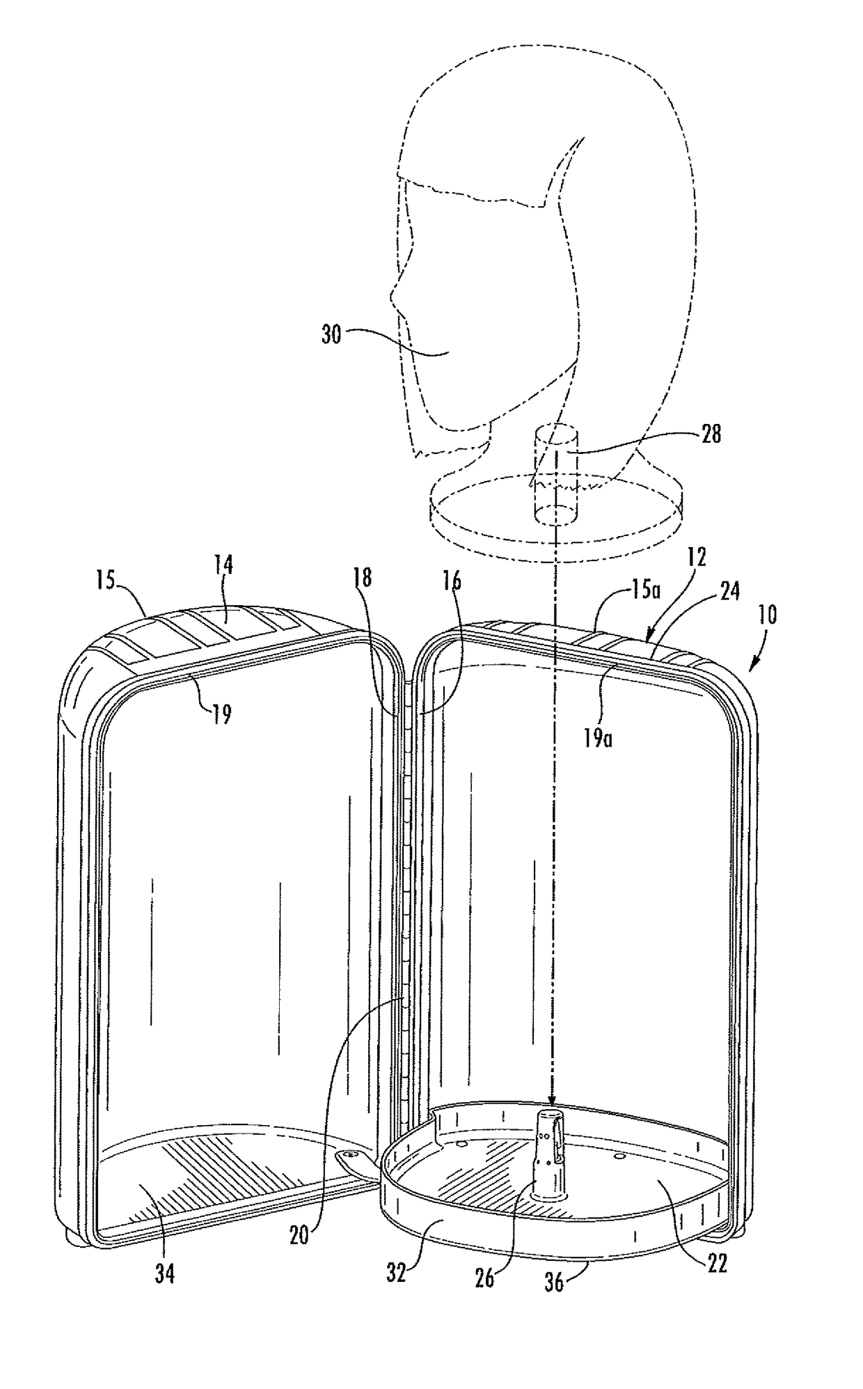
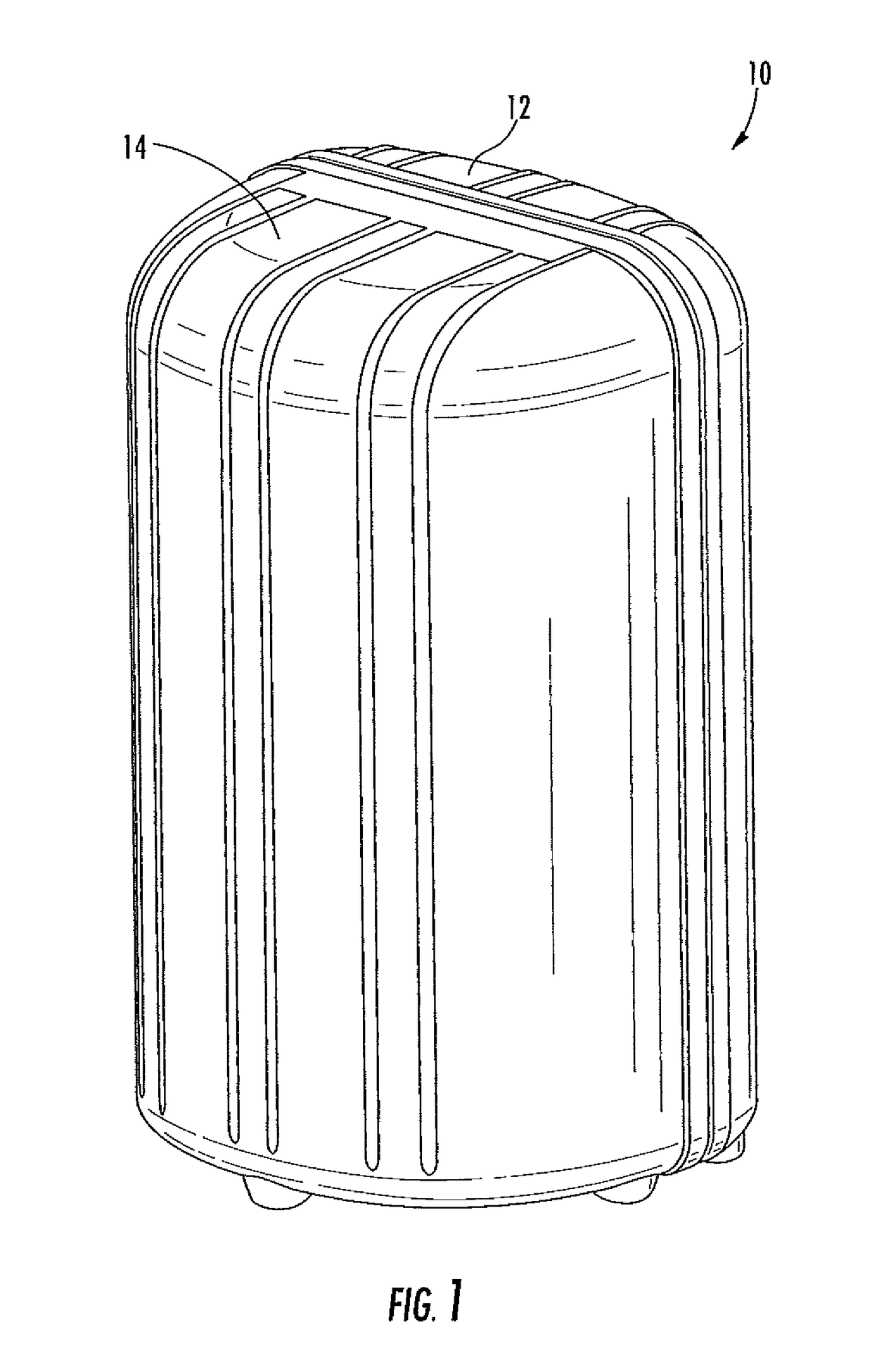
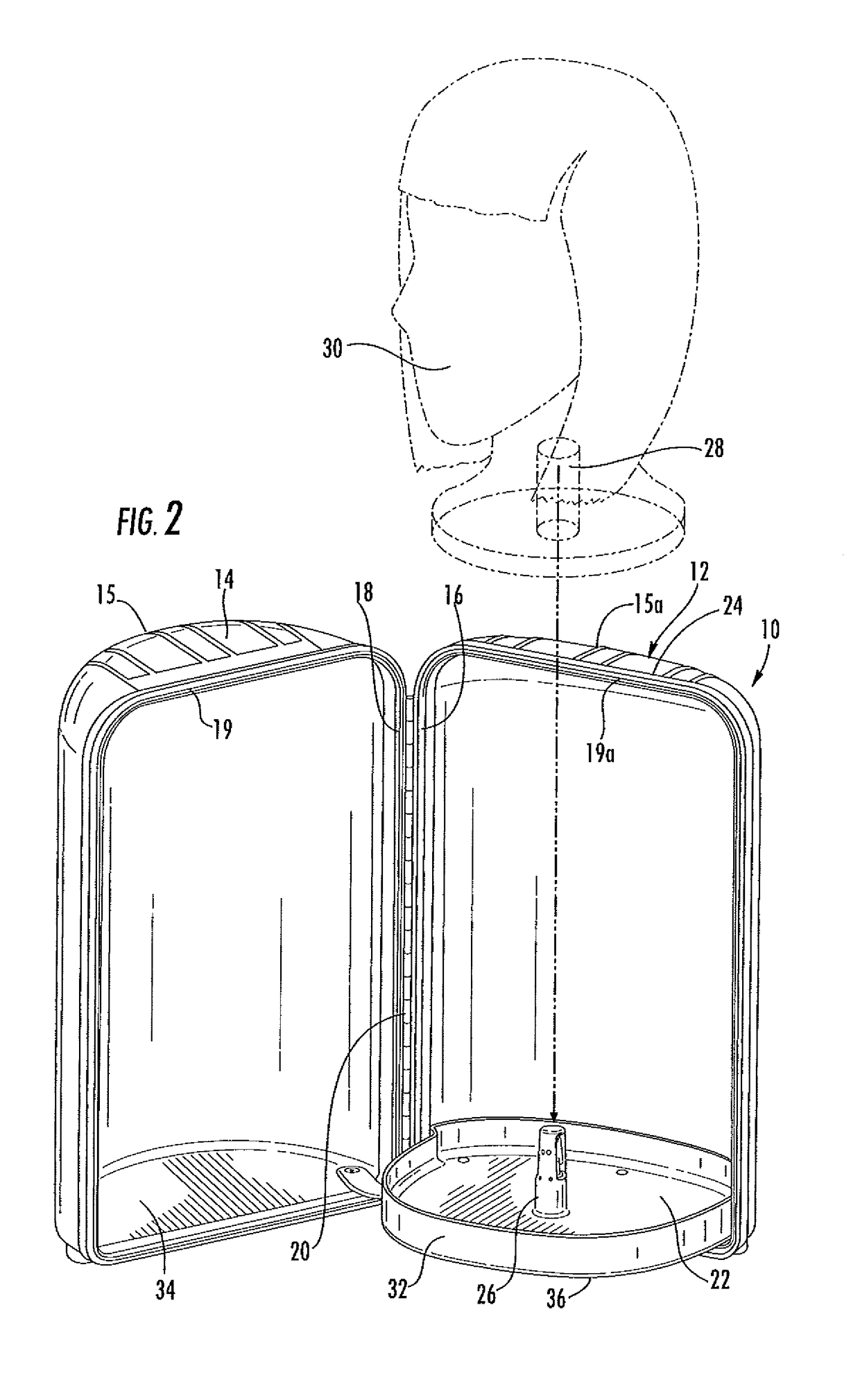
[0014]FIG. 1 shows a wig carrier 10 that is fastened closed according to an embodiment of the invention. As shown, carrier 10 is a generally elongated housing that is made of two corresponding panels 12, 14. Panels may be formed of hard plastic or similar lightweight material. First panel 12 and second panel 14 are joined by way of a hinge or si...


PUM


Abstract

A carrying case for a wig. The case is made of two panels that are joined together by hinges. One panel has a floor surface that extends in a lateral direction past a roof section. The floor surface has a post for receiving a wig head. Contact members are deployable to protrude from the post and burrow into or otherwise press against the inside walls of a channel provided in a wig head.

Description

RELATED APPLICATIONS[0001]This application claims the benefit of U.S. Prov. Appl. Ser. No. 61 / 992,371 filed May 13, 2014 and U.S. Prov. Appl. Ser. No. 61 / 918,983 filed Dec. 20, 2013 the contents of which are incorporated by reference herein.FIELD OF THE INVENTION[0002]The invention relates to the field of luggage devices, more specifically to a case for carrying and securing a wig on a wig head.BACKGROUND OF THE INVENTION[0003]Many people wear wigs for various reasons, ranging from health reasons to religious considerations. Wigs are delicate items and they must be handled carefully in transport. The carrying cases for wigs currently available on the market are unwieldy and they not user friendly. For example, currently available wig carriers are generally square or rectangular cases that have an outwardly opening door. The door occupies space when the carrier is open and a wig head must be slid into the box in a lateral direction. In addition, current wig carriers do not allow for ...

Claims


Application Information

Patent Timeline
Patent Type & Authority Patents(United States)
IPC IPC(8): A45C11/02A45C13/02A45C5/08A45C13/00A45C11/00
CPCA45C13/02A45C5/08A45C11/00A45C13/005
Inventor ROSENBLATT, ELICOWAN, DAVIDZELNICK, BENJAMIN
Owner ROSENBLATT ELI
Why Eureka
Try Eureka