Metering dispenser

a metering and dispenser technology, applied in the direction of spraying apparatus, single-unit apparatus, packaging, etc., can solve the problems of large volume of these products, complicated structure of pump units and their support on the cartridge outlet, and small dosage volume in comparison to the prior, so as to reduce the number of moving parts, simple and stable structure, and solid construction

Active Publication Date: 2017-04-04
HOLZMANN WERNER
View PDF10 Cites 0 Cited by
  • Summary
  • Abstract
  • Description
  • Claims
  • Application Information

AI Technical Summary

Benefits of technology

[0005]In comparison to the above-described dispensers the inventive solution has a particularly simple and stable structure, as the pump unit is guided in the upper portion of the cartridge or the container in a sleeve. By this sleeve in continuation with the cartridge the component to be metered can easily pass the inlet and outlet valve of the pump unit. Further, this arrangement allows to stabilize the guide of the pump piston or the support of the pump cylinder and to reduce the number of moving components. Preferably, the pump unit is made as a one-piece injection-molded part.
[0006]It is particularly advantageous that the pump piston or pump cylinder of each pump unit can be mounted to the sleeve on the container very easily and having a solid construction with low height. Preferably, the sleeve is integrally formed on the container by injection molding. In addition, the sleeve includes in its interior ring beads or undercuts for latching with the pump cylinder and / or the pump piston. Thus, the pump cylinder is securely anchored in the sleeve or pressed-in, so that the bottom of the pump cylinder can securely fix or clamp an inlet valve, in particular in the form of a membrane.
[0007]Particularly important is the design of the spring for the outlet valve, which is arranged on a fold-down spring clip, wherein the latter is preferably connected to the pump piston in one piece by injection molding. Here, the spring clip has a film hinge and opposite thereto a locking pin, so that a simple, cost-effective manufacture and assembly is obtained. Here, the spring may also consist of plastic and is integrally formed in a meander shape on molding of the spring clip, so that a very simple structure is achieved.

Problems solved by technology

Further, the dosage volume of these products is very small in comparison to the prior art.
Moreover, these products are highly viscous, thus requiring a pump with a small “dead volume” and wide valve opening relative to the dosage volume.
These known dispensers are well-established in the market, but they still have disadvantages.
In particular, the pump units and their support on the cartridge outlet have a rather complicated structure.

Method used


Image

  • Metering dispenser
  • Metering dispenser
  • Metering dispenser

Examples


Embodiment Construction

[0012]The following description is provided to enable any person skilled in the art to make and use the invention and sets forth the best modes contemplated by the inventor of carrying out his invention. Various modifications, however, will remain readily apparent to those skilled in the art, since the general principles of the present invention have been defined herein specifically to provide an improved metering dispenser.

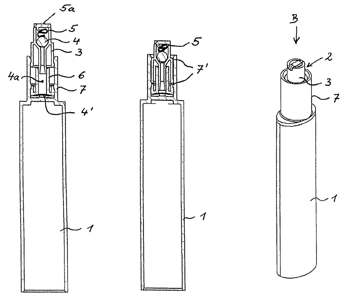
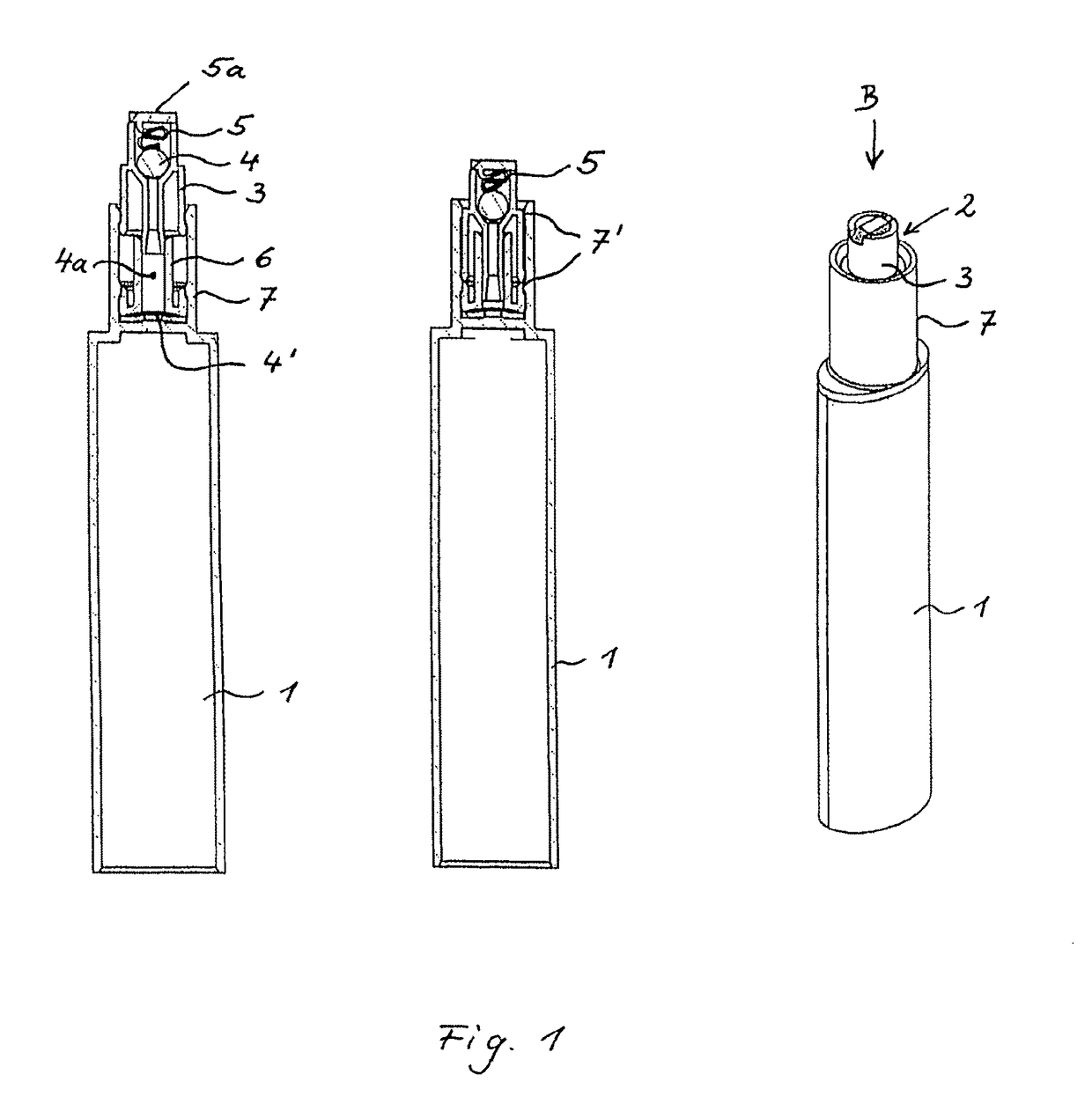
[0013]With reference to the perspective view in FIG. 1, the basic concept of a metering dispenser is described, which consists of a container 1, here a cartridge with oval or semicircular shape, and a pump unit 2. In a dispenser, two or more of such containers 1 may be provided, each with a respectively associated pump unit. Advantageously, adjustment of the mixture of the individual components in the containers 1 can be carried out by turning a non-illustrated actuator. In many applications, however, a fixed setting of the mixing ratio is sufficient. The output ...


PUM


Abstract

A cost-effective metering dispenser configured to allow at least one component accommodated in a container, in particular in cartridge form, to be metered by a pumping unit, having an inlet valve, an outlet valve and a pumping cylinder as well as a pumping piston, which is inserted in the pumping cylinder and can be activated by an actuating element. The dispenser is economical to produce because of the straightforward construction of the pumping unit, that can be arranged in a sleeve, which continues the container and is formed in one piece with the container.

Description

AREA OF THE ART[0001]The invention relates to a metering dispenser.DESCRIPTION OF THE BACKGROUND[0002]The prior art discloses such dispensers, wherein the mixing ratio of two components is continuously adjustable. Such a dispenser can be used, for example as a lip care dispenser to mix two components with different tints such that the color can be continuously adjusted over a wide range. The dimensions of such dispensers for these products are rather small such that a compact design of all components, especially of the pump unit is needed. Further, the dosage volume of these products is very small in comparison to the prior art. Moreover, these products are highly viscous, thus requiring a pump with a small “dead volume” and wide valve opening relative to the dosage volume. In order to achieve these requirements with a precise dosage, the valve must close very exactly and automatically to avoid product return. Furthermore, production cost should be low by using fewer parts and easy ...

Claims


Application Information

Patent Timeline
Patent Type & Authority Patents(United States)
IPC IPC(8): B65D88/54B05B11/00
CPCB05B11/3025B05B11/0064B05B11/3046B05B11/3016B05B11/3023B05B11/3084B05B11/1046B05B11/1084B05B11/1025B05B11/1016B05B11/1023
Inventor HOLZMANN, WERNER
Owner HOLZMANN WERNER
Why Eureka
Try Eureka