Optimizing and controlling the energy consumption of a building

a technology for optimizing and controlling the energy consumption of buildings, applied in the direction of program control, instruments, heating types, etc., can solve the problem that the system is generally not capable of accounting for the thermal characteristics, and achieve the desired comfort level, improve the efficiency of energy consumption and monitoring, and optimize the energy use of buildings

Active Publication Date: 2017-04-04
UNIV OF MARYLAND +1
View PDF37 Cites 8 Cited by
  • Summary
  • Abstract
  • Description
  • Claims
  • Application Information

AI Technical Summary

Benefits of technology

[0005]The techniques described herein relate to optimizing energy use of a building (e.g., home) by dynamically controlling comfort devices of the building (such as thermostats, fans, shades, doors, windows, humidifiers, appliances, other heating / cooling systems) to change the comfort characteristics of the building such as pre-heating, pre-cooling, and the like in response to local weather forecast conditions and when a demand response event is anticipated. In addition, the techniques provide the advantage of maintaining a desired comfort level for occupants of the building while encouraging efficient energy usage and monitoring.

Problems solved by technology

The automatic adjustment of temperature may be conducted by a utility that provides power to the home, but often such adjustments are based on incomplete or inaccurate weather information for the precise location of the home and do not factor in the occupant's personal preferences.
In addition, these systems are generally not capable of accounting for the thermal characteristics of the particular building in which the thermostat is installed.

Method used


Image

  • Optimizing and controlling the energy consumption of a building
  • Optimizing and controlling the energy consumption of a building
  • Optimizing and controlling the energy consumption of a building

Examples


Embodiment Construction

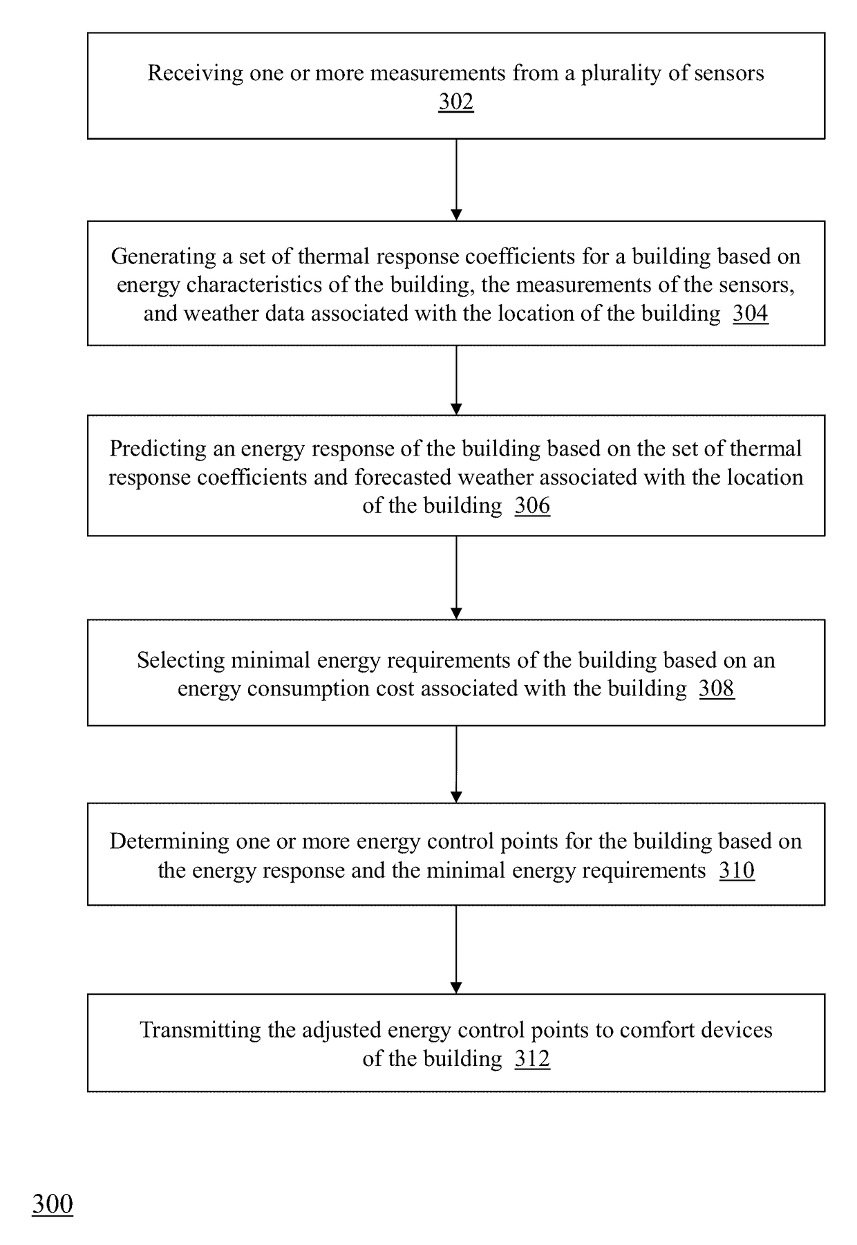
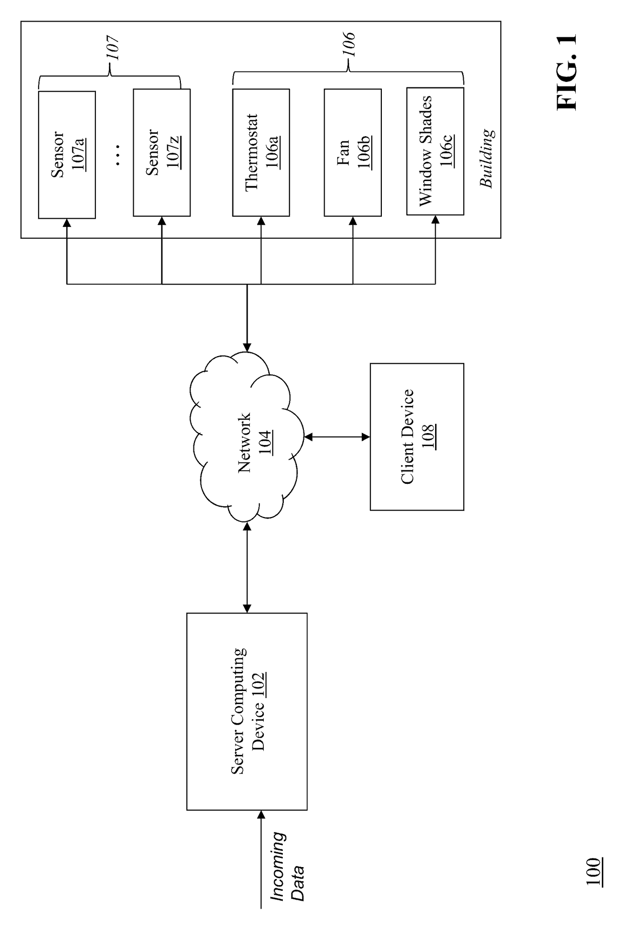
[0028]FIG. 1 is a block diagram of a system 100 for optimizing and controlling the energy consumption of a building. The system 100 includes a server computing device 102, a communications network 104, a plurality of comfort devices 106 (e.g., a thermostat device 106a that controls the heating and / or cooling apparatus for the building, other comfort devices such as a fan 106b and window shades 106c), a plurality of sensor devices 107a-107z (collectively, 107), and a client computing device 108. The server computing device 102 receives data from external sources (e.g., weather data, thermostat data from thermostat 106a, sensor data from sensors 107) and determines energy response characteristics and energy requirements for a particular building. The server computing device 102 determines energy control points for the building, and transmits the energy control points to comfort devices 106 in the building (e.g., thermostat 106a, fan 106b, window shades 106c) via the network 104 so tha...


PUM


Abstract

Described herein are methods and systems, including computer program products, for optimizing and controlling a building's energy consumption and comfort. A computing device receives measurements from a plurality of sensors, at least some of which are located inside the building, where the measurements include temperature readings and comfort characteristics. The computing device generates a set of thermal response coefficients based on energy characteristics of the building, the measurements from the sensors, and weather data associated with the building's location. The computing device predicts an energy response of the building based on the set of thermal response coefficients and forecasted weather. The computing device selects minimal energy requirements of the building based on an energy consumption cost associated with the building and determines energy control points based on the energy response and the minimal energy requirements. The computing device transmits the energy control points to comfort devices in the building.

Description

RELATED APPLICATIONS[0001]This application is a continuation-in-part of U.S. patent application Ser. No. 13 / 729,501, filed Dec. 28, 2012, which claims priority to Ser. No. 61 / 589,639, filed on Jan. 23, 2012, the entire disclosure of which is incorporated herein by reference.TECHNICAL FIELD[0002]The technology relates generally to optimizing and controlling the energy consumption of a building.BACKGROUND[0003]Weather is the largest variable impacting home energy demand Many homes are equipped with a standard thermostat to regulate heating and cooling, where the occupant either manually adjusts the temperature to account for weather conditions or the thermostat automatically adjusts temperature based on a predetermined schedule. The automatic adjustment of temperature may be conducted by a utility that provides power to the home, but often such adjustments are based on incomplete or inaccurate weather information for the precise location of the home and do not factor in the occupant's...

Claims


Application Information

Patent Timeline
Patent Type & Authority Patents(United States)
IPC IPC(8): G05B13/02G05B15/02F24F11/00
CPCG05B15/02F24F2011/0013G05B2219/2639G05B2219/2642Y04S20/244G05D23/1917F24F2110/12
Inventor SLOOP, CHRISTOPHER DALEOBERHOLZER, DAVIDMARSHALL, ROBERT S.KIM, JUNGHOSIEMANN, MICHAEL
Owner UNIV OF MARYLAND
Why Eureka
Try Eureka