Interconnection seal

a technology of interconnection and seal, which is applied in the direction of cable termination, coupling device connection, other domestic objects, etc., can solve the problems of difficult opening, gel seals are typically not re-usable, and electrical interconnections are subject to degradation

Active Publication Date: 2017-04-11
COMMSCOPE TECH LLC
View PDF51 Cites 13 Cited by
  • Summary
  • Abstract
  • Description
  • Claims
  • Application Information

AI Technical Summary

Benefits of technology

[0034]The connector neck seal portion 17 is configured to seal against the neck portion 21 of the connector interface 23, for example, that a coupling nut 25 of the connector 19 is threaded upon. The connector interface 23 may be provided as a bulkhead type connection point, as shown for example in FIGS. 9 and 13, which includes a bulkhead surface 22 transverse to the longitudinal axis of the connection interface 23. The coupling nut cavity portion 15 is provided with a greater inner diameter than the connector neck seal portion 17. Thereby, the coupling nut cavity portion 15 can surround the coupling nut 25 and the connector neck seal portion 17 can engage and seal against the neck 21 of the selected connector interface 23, without requiring a non-standard connection interface with an increased connector neck diameter.
[0035]One skilled in the art will appreciate that the connector neck seal portion 17, extending between the coupling nut 25 and the bulkhead surface 22, provides an extended surface for the connector neck seal portion 17 to seal against, which may improve the resulting seal. Further, a connector end of the connector neck seal portion 17 which transitions into the bulkhead seal 20 provides a ready pull surface for momentarily stretching the connector neck seal portion 17 over the coupling nut 25 during installation and then aligning the connector neck seal portion 17 into position. The bulkhead seal 20 also provides additional seal surface area and may further operate to bias the connector neck seal portion 17, between the cable end of the coupling nut 25 and the bulkhead surface 22, into sealing engagement with the neck 21. For ease of grip, the bulkhead seal 20 may be provided with an outer diameter greater than an outer diameter of the connector neck seal portion 17, for example equal to or greater than an outer diameter of the coupling nut cavity portion 15.
[0041]The cable outer diameter seal portion 11 and / or connector neck seal portion 17 may be provided with a smooth cylindrical inner sidewall. Thereby, the contact area between the cable outer diameter seal portion 11 and the outer diameter of the cable 31 and / or between the connector neck seal portion 17 and a neck 21 of the connector interface 23 is maximized, so that the seal therebetween has the largest possible contact area to resist leakage, and any leakage that does occur is not provided with areas within which liquid may pool along the extent of the respective sealing surfaces. Further, the close contact between the seal and the interconnection along the length of the interconnection minimizes formation of any cavities within the seal where moisture may pool over time, for example via condensation.
[0043]The presence of the grip fins 27 and or grip tabs 29 may assist the stretching of the seal for installation and / or removal by providing ready grip surfaces as each portion of the seal is advanced over the interconnection 10. Because the grip fins 27 and / or grip tabs 29 have a limited circumferential extent, they do not inhibit deformation of the various portions of the seal for momentary stretching / advancement over the interconnection 10.
[0045]The body 3 may be manufactured, for example by injection molding, from one of a liquid injection molded silicone rubber, liquid silicone rubber, thermoplastic elastomer and molded closed-cell foam. Elastic properties of these materials may enable molding without utilizing cost prohibitive collapsing core mold portions. Further, aligning the grip fins 27 and / or grip tabs 29 with the mold separation plane may simplify mold separation and / or minimize the appearance of any edge flash that may be present.
[0046]From the foregoing, it will be apparent that the seals bring to the art an improved seal useful, for example, for re-usable sealing of bulkhead type interconnections of standard connector interfaces. The resulting seals may further enable significant manufacturing and / or installation efficiencies.

Problems solved by technology

Electrical interconnections are subject to degradation from environmental factors such as moisture, vibration and repeated expansion and contraction from daily temperature changes.
The prior enclosures typically apply rigid clamshell configurations which, once closed, may be difficult to open, especially when installed in exposed locations such as atop radio towers.
Gel seals are typically not re-usable and / or have only a limited number of re-uses before they must be replaced.
Because the connector body or other connection assembly is typically a bulkhead type, flush against a surface, a cable-to-cable interconnection sealing assembly that tapers at either end to the same cable diameter is unusable.
However, the seal area along the periphery of the C-shaped body is extensive, which may degrade the long term performance of the resulting seal.

Method used


Image

  • Interconnection seal
  • Interconnection seal
  • Interconnection seal

Examples


Embodiment Construction

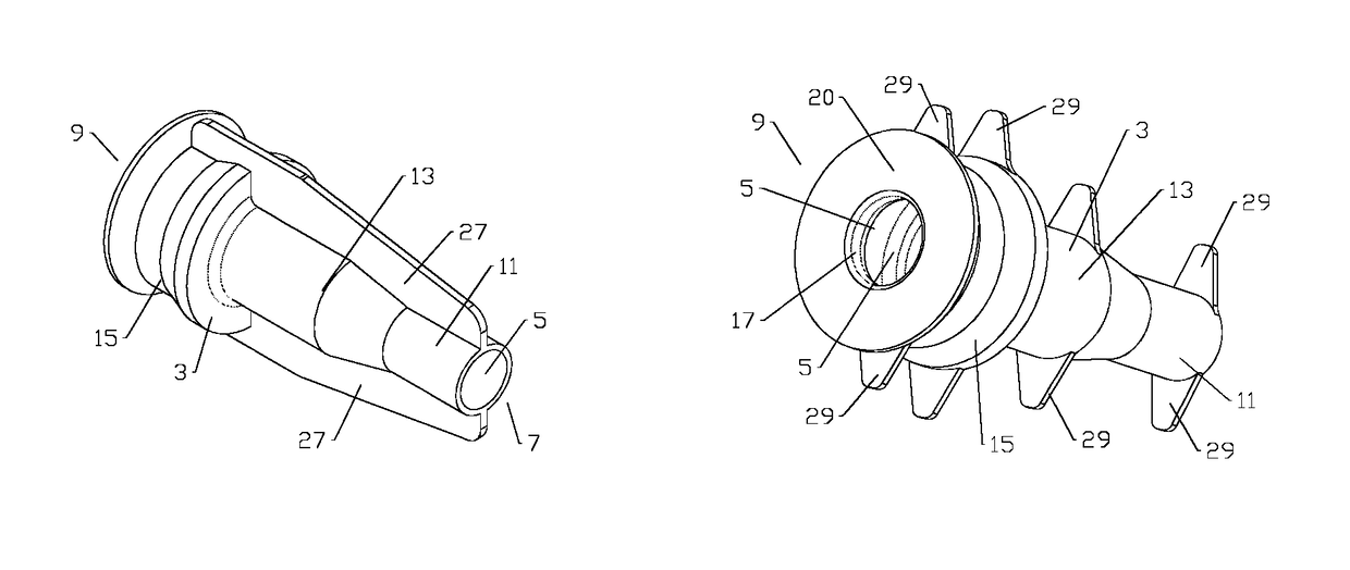
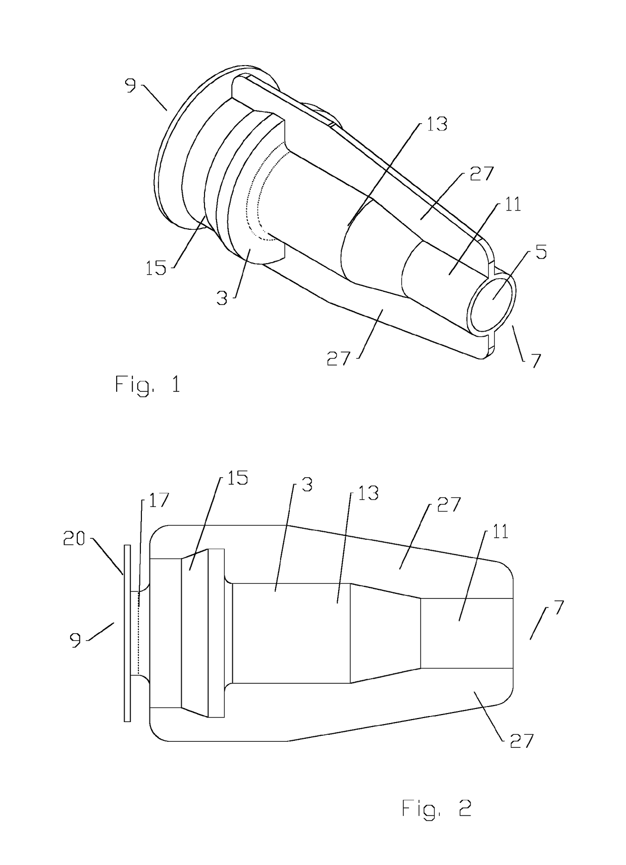
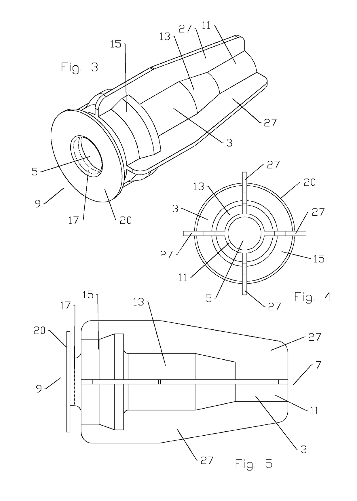
[0032]As shown for example in FIGS. 1-19, a seal has a unitary elastic body 3 with a bore 5 therethrough. Sequenced from a cable end 7 to a connector end 9, the bore 5 has: (a) a cable outer diameter seal portion 11 at the cable end 7; (b) the cable outer diameter seal portion 11 adjacent a connector cavity portion 13; (c) the connector cavity portion 13 adjacent a coupling nut cavity portion 15; (d) the coupling nut cavity portion 15 adjacent a connector neck seal portion 17 and (e) a bulkhead seal (20) adjacent the connector neck seal portion 17, at the connector end 9.

[0033]One skilled in the art will appreciate that cable end 7 and connector end 9 are provided as position references for both the interconnection and individual elements of the connector and seal portions along a longitudinal axis of the interconnection 10. Therefore, each element identified has both a cable end 7 and a connector end 9, these being the sides of each element closest to the cable end 7 and the connec...


PUM

PropertyMeasurementUnit
outer diameteraaaaaaaaaa
inner diameteraaaaaaaaaa
circumferenceaaaaaaaaaa

Abstract

A seal for a cable and connector interconnection includes a unitary elastic body with a bore therethrough. The bore is provided with a cable outer diameter seal portion at a cable end, the cable outer diameter seal portion adjacent a connector cavity portion, the connector cavity portion adjacent a coupling nut cavity portion, and the coupling nut cavity portion adjacent a connector neck seal portion with a bulkhead seal at a connector end. The coupling nut cavity portion is longitudinally aligned with a coupling nut of the connector and is provided with a greater inner diameter than the cable outer diameter seal portion and the connector neck seal portion. The bulk head seal is provided with an outer diameter greater than an outer diameter of the connector neck seal portion.

Description

BACKGROUND[0001]Field of the Invention[0002]The invention relates to a device for environmentally sealing and securing the interconnection between cables and / or apparatus, for example between feed and / or control cables interconnected with an apparatus or enclosure.[0003]Description of Related Art[0004]Electrical interconnections are subject to degradation from environmental factors such as moisture, vibration and repeated expansion and contraction from daily temperature changes.[0005]Environmental seals, such as outer sealing enclosures that surround an electrical interconnection, have been used, for example, to surround a cable end connector to cable end connector interconnection.[0006]The prior enclosures typically apply rigid clamshell configurations which, once closed, may be difficult to open, especially when installed in exposed locations such as atop radio towers. Gaskets may be applied at the enclosure ends and / or along a sealing perimeter of the shell. Gel seals are typical...

Claims


Application Information

Patent Timeline
Patent Type & Authority Patents(United States)
IPC IPC(8): H01R13/52H02G1/14B29C45/00B29K83/00B29K105/04B29L31/00B29L31/36
CPCB29C45/0001H02G1/14B29K2083/005B29K2105/046B29L2031/36B29L2031/7278Y10T29/49176H01R13/5205H01R4/70B29K2083/00H02G15/04
Inventor VACCARO, RONALD A
Owner COMMSCOPE TECH LLC
Why Eureka
Try Eureka