
Surgical instrument, in particular pointer instrument, comprising tip sensor

a technology of pointer and tip sensor, which is applied in the field of surgical instruments, can solve the problems that the use of such an instrument with a navigation system is in most cases still very operatively intensive, and achieve the effect of simple and user-friendly handling with a medical navigation system

Active Publication Date: 2017-04-18
BRAINLAB
View PDF23 Cites 11 Cited by
  • Summary
  • Abstract
  • Description
  • Claims
  • Application Information

AI Technical Summary

Benefits of technology

[0005]It is the object of the present invention to provide a surgical instrument, in particular a pointer instrument, which makes handling with a medical navigation system simple and more user-friendly.
[0007]In accordance with the present invention, a surgical instrument is thus provided, in particular a pointer instrument, which comprises a handle portion and a tip, and a tip sensor on the handle portion. The tip sensor is so-called because it detects various features which are associated with the tip of the instrument and which are explained in more detail below. In other words, the handle portion of the instrument in accordance with the invention is embodied such that it can detect information concerning the instrument tip, and precisely this characteristic of the instrument in accordance with the invention makes handling it very much simpler. For various information concerning the tip and / or its cooperation or interaction with the handle can be used in order to make navigation simpler, less elaborate and more user-friendly, because such information (for example concerning the type of tip or the current load on the tip) can replace information inputs which otherwise have to be made on the navigation system by the user.
[0009]In accordance with one embodiment of the present invention, at least one tip can be removably fastened to the handle portion, in particular using a releasable fastening, specifically a plug fastening. A number of tips can be exchangeably fastened to the handle portion, specifically by means of a fastening adaptor which is the same for a number of tips or for all the tips and allows the tips to be simply fastened and therefore also simply exchanged. Once fastened, the tip should sit on the handle rigidly and with zero tolerance.
[0013]In accordance with another aspect of the present invention, the tip sensor comprises a force sensor for the force exerted by a tip on the handle portion. Using this force sensor, it is possible to detect whether the tip is currently pressing against a resistance and therefore whether the instrument is currently ready for use or is being used. It is thus possible for example to determine whether the tip is currently being moved to a landmark in order to detect its position. Detecting the force also allows detection over a longer period of time, such that it is possible to determine whether for example a pointer tip is sliding over a surface in order to detect its contour. The contour would then only be detected as long as a force by the tip on the handle is measured. When the instrument is removed from the surface, a force is also no longer exerted, and this can immediately and automatically switch off the contour detection in the navigation system.
[0026]Different buttons for controlling the navigation software can be attached to the handle, i.e. for example push-buttons, rocker switches or turning knobs (one to three, especially two to three buttons). They can be mechanical or electromechanical in nature or can be sensor buttons. They can have a tactile pattern on their surface so that they can be easily operated using surgical gloves.

Problems solved by technology

On the other hand, using such an instrument with a navigation system is in most cases still very operatively intensive, because the user always has to inform the navigation system that he is currently moving to a landmark, such that its position can be recorded and / or stored.
If a number of points are successively recorded or a contour profile is continuously traveled using the pointer tip, difficulties can result because the navigation system constantly has to be informed as to whether the pointer tip is currently lying on the contour to be scanned or is being lifted and transferred to another location.

Method used


Image

  • Surgical instrument, in particular pointer instrument, comprising tip sensor
  • Surgical instrument, in particular pointer instrument, comprising tip sensor
  • Surgical instrument, in particular pointer instrument, comprising tip sensor

Examples


Embodiment Construction

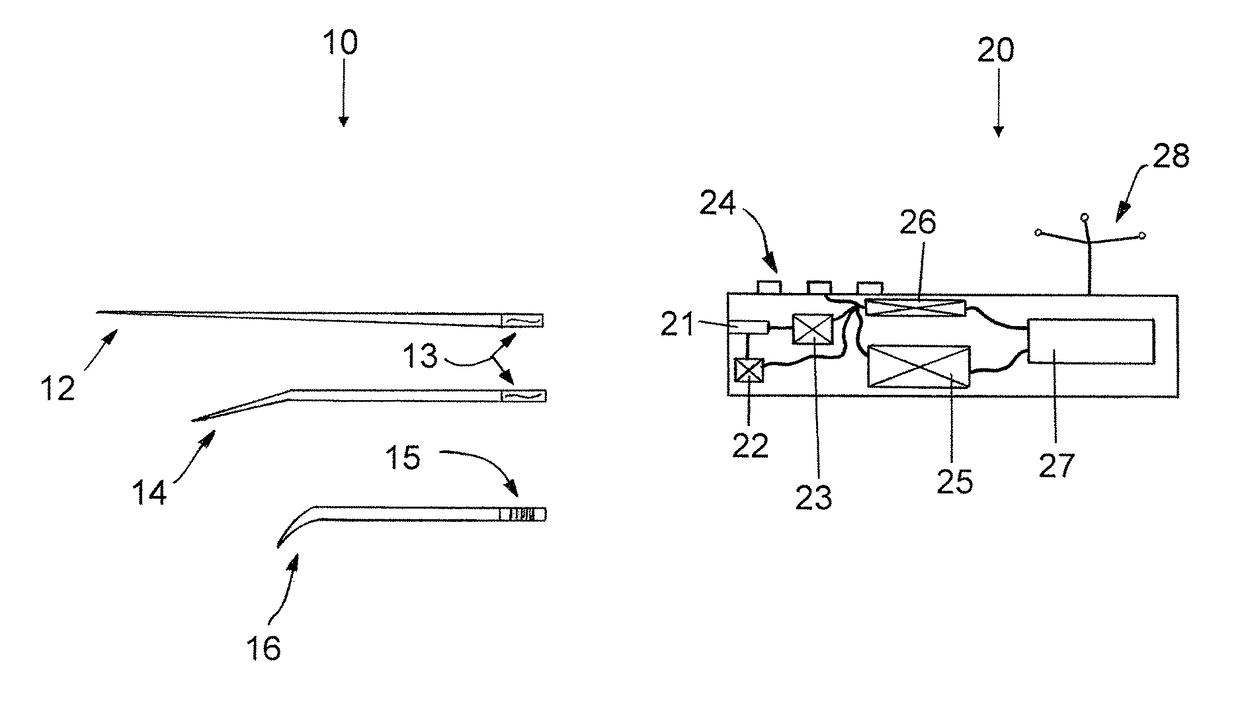
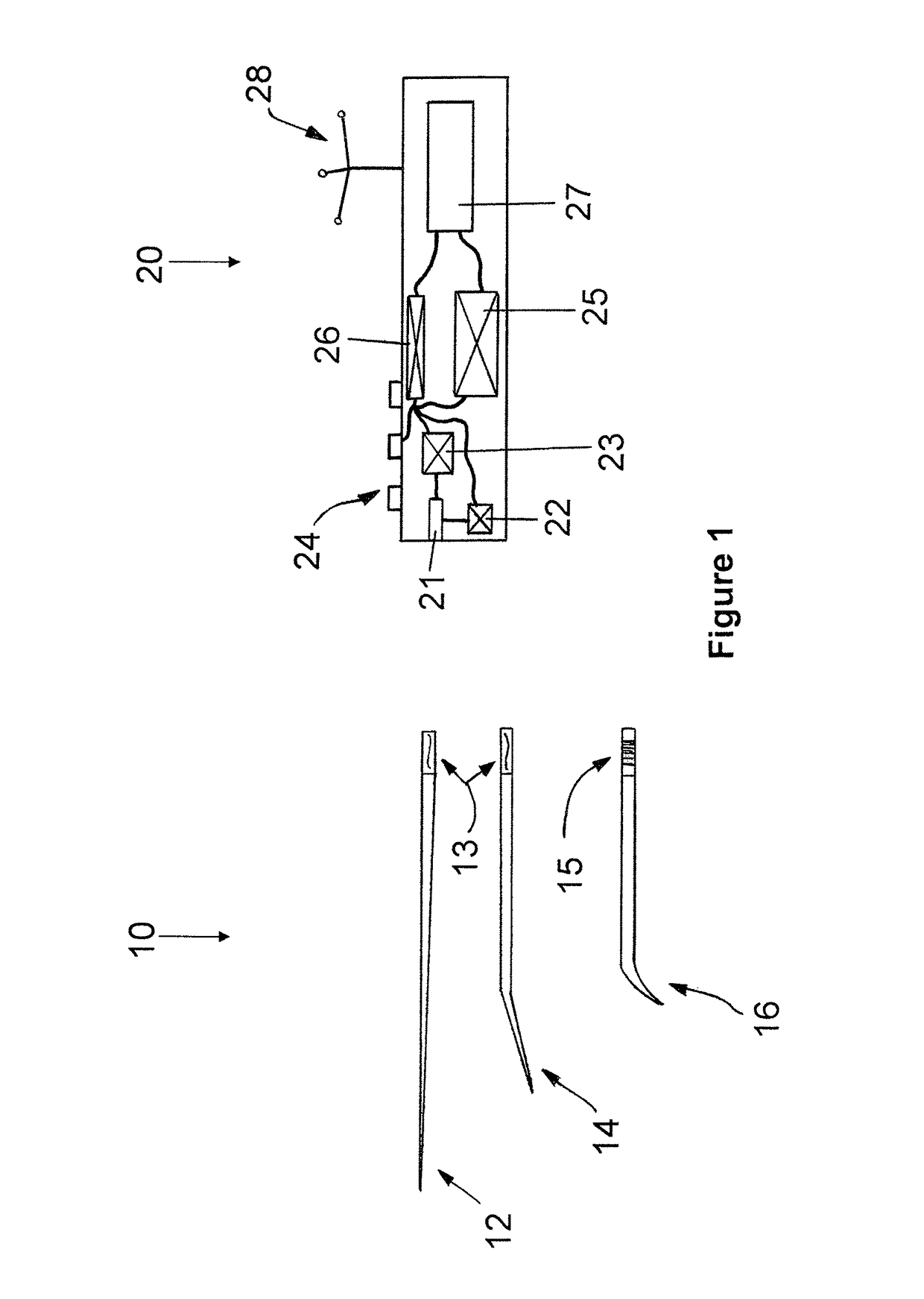
[0032]FIG. 1 shows different alternatives of a surgical instrument, i.e. comprising different tips 12, 14, 16 (wherein the reference sign 10 is also used as a whole for the tip in general) and a handle portion 20. The tips can be different tips for a surgical pointer, wherein the tip 12 is a long straight tip, the tip 14 is a tip comprising an angled front part and the tip 16 is a rounded tip. All the tips have a fastening portion at the end opposite their front end, and in the case of the tips 12 and 14, this fastening portion 13 is formed as a key shape portion. The instrument tip 16 has a fastening portion 15 which has been provided with an engraved or imprinted barcode. The fastening portions 13, 15 serve on the one hand to fasten the tip to the handle, and on the other hand to identify the tip and to provide data, i.e. shape data, concerning the tip. Thus, the key portion 13 can comprise this data by mechanical shaping, while in the barcode of the portion 15, the data is accomm...


PUM


Abstract

The invention relates to a surgical instrument comprising a handle portion and a tip, wherein a tip sensor is provided on the handle portion. The tip sensor enables detection of when a tip is inserted into and / or removed from the handle. In addition, the tip sensor enables a navigation system to be notified when landmarks are probed with the surgical instrument, thereby ensuring accurate capture of the location of the landmark.

Description

RELATED APPLICATION DATA[0001]This application claims the priority of U.S. Provisional Application No. 61 / 104,799, filed on Oct. 13, 2008, which is hereby incorporated in its entirety by reference.FIELD OF THE INVENTION[0002]The invention relates to a surgical instrument, in particular a pointer instrument.BACKGROUND OF THE INVENTION[0003]Pointer instruments are widely used especially in the field of medical navigation, wherein this also applies to the instruments in accordance with the invention as described here. One specific type of use is to move the tip of the pointer instrument to points on the patient (landmarks) or on medical auxiliary devices, wherein calibrated or pre-calibrated pointer instruments are localized with the aid of a medical tracking system (for example via cameras and position markers on the instrument); the position of the tip of the instrument is thus known and therefore also the position of the landmark or, in very general terms, the point to which the poi...

Claims


Application Information

Patent Timeline
Patent Type & Authority Patents(United States)
IPC IPC(8): A61B90/96A61B90/98A61B90/00A61B34/20A61B17/00
CPCA61B90/96A61B34/20A61B90/98A61B2017/00411A61B2017/00464A61B2017/00482A61B2017/00734A61B2034/2051A61B2034/2068A61B2090/064A61B2090/065A61B2090/0806
Inventor BIRKENBACH, RAINERVILSMEIER, STEFAN
Owner BRAINLAB
Learn More