[0006] An object of the invention is therefore to specify a method which permits simple navigation and as a result rapid examination and location of the relevant pathological sites, especially the “Vulnerable Plaques”, to lessen the risk to the patient and reduce
exposure to
radiation during necessary execution of the invasive method to examine the hollow organ.
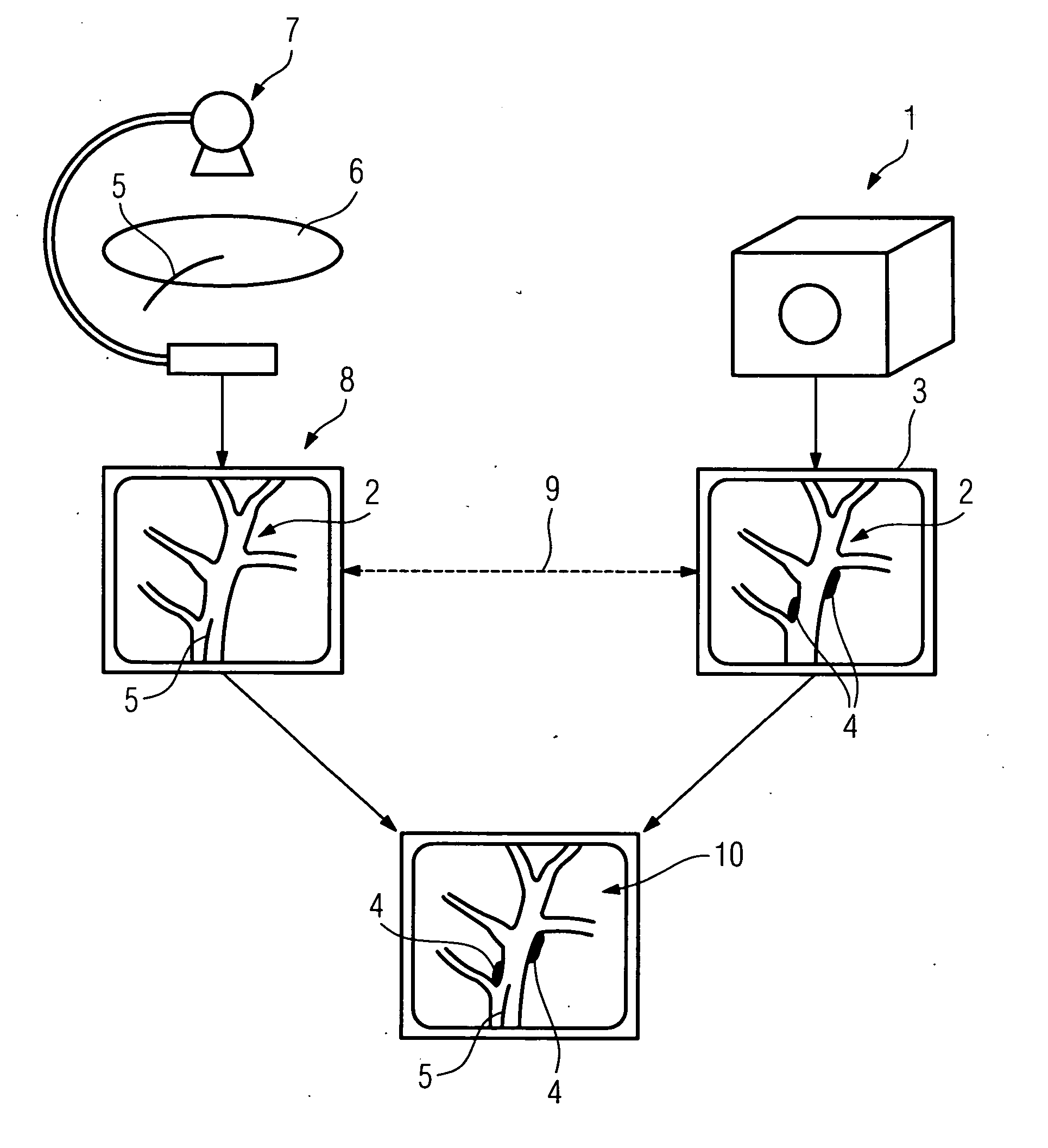
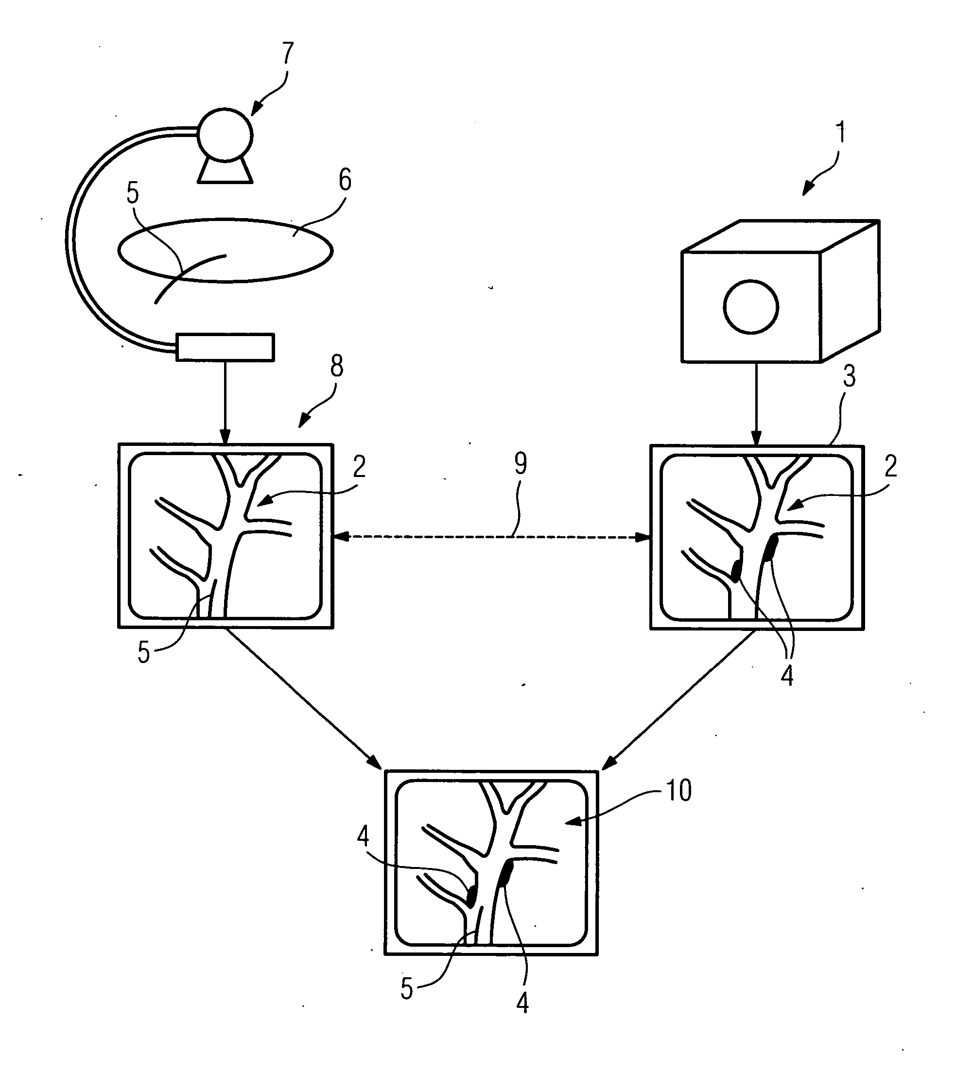
[0008] The solution according to the invention is for successive use of a non-invasive
examination procedure such as, for example, a magnetic
resonance or computer
tomography examination and an invasive
examination procedure (such as, for example, IVUS or O CT examinations) which each provide separate image displays, containing different statements, of the hollow organ or of the recorded part. Via the first, non-invasively recorded image display, e.g. the MR or the CT image, the “Vulnerable Plaques” can be located in the image by means of larger inflammatory processes, i.e. information is obtained about the position of the pathological sites in the hollow organ. This image display is reproduced during the invasive examination. This means that the doctor providing the treatment has continuous knowledge of the precise location of the sites of interest to which the catheter is to be routed. Navigation is now made still easier for him by the performance of an X-
ray angiography control and the angiography image also being displayed continuously in parallel with the movement of the catheter. In this way the doctor can without further action immediately compare the actual position of the catheter tip and the actual location of a “
Vulnerable Plaque” toward which to move. The movement of the instrument can be controlled manually, computer-aided or entirely computer-controlled.
[0009] Owing to the possibility of considerably more efficient and more specific navigation, the risk always associated with the invasive
examination method is considerably reduced for the patient as it is no longer necessary to examine all the possible vascular branches in order to locate the plaque, since a pathological site can be approached specifically. This means that the duration of the invasive examination is considerably reduced. Inevitably this also applies to the duration of
exposure to
radiation resulting from the angiography control examination. In order to make recording of the pathological sites easier for the doctor to locate on the monitor in the first image display, it is expedient if the pathological site or sites are highlighted in the first image display. This highlighting, e.g. by means of color highlighting, can for example be done by the user himself by first assessing the image recorded non-invasively before the invasive examination and highlighting the pathologically relevant sites on the monitor, for example, using the usual monitor cursor and suitable editing
software. As an alternative to manual highlighting, it is also conceivable to locate the pathological sites automatically in the image using a suitable
image analysis system based on suitable analysis algorithms, i.e. highlighting is done automatically, insofar as the image display or
pathology permits this.
[0010] With regard to simple recording of the image information in the first image display as well as the angiography image display, an advantageous development of the invention envisages that the multidimensional form of the first image display corresponds to that of the angiography image display. The angiography images are two-dimensional, for which reason the first display, obtained from, for example, the MR or the
CT examination, is also two-dimensional. If the MR or CT data
record is three-dimensional, the corresponding two-dimensional projection is calculated and displayed from it as appropriate. Furthermore, a position data
record using a position
recording system can be made, for example, for each individual angiography image, for which purpose a corresponding
position sensor is used in the catheter, which permits the recording of a movement by preferably
six degrees of freedom (in x, y and z direction of the coordinate axes as well as by the respective rotation around this axis). From this the spatial location of the catheter in the MR or CT display is possible, which can then also be indicated as a 3D-image in addition.
[0011] A particularly advantageous development of the invention envisages registering the first image display and the angiography image display with one another and displaying them merged together. After this the angiography image is overlaid on the MR or CT image or on the respective
cutting plane display. In this way, the doctor obtains information about the
anatomy of the examination area from the MR or CT display, and he obtains the information about the actual position of the catheter tip from the overlaid angiography image display. On account of the registration of both image displays, it is always possible to insert the angiography image precisely into the MR or CT image, even where there is constant catheter movement and as a result a constant change in the recording position, and thus enable a constantly adapted, “co-moved” fusion display.
[0013] As an alternative to registration on the basis of the anatomical landmarks, registration can take place via position data continuously obtained for each recorded angiography image display, which indicates the position and / or orientation of the instrument in the coordinates
system of the position
recording system, which provides the basis for the registration of the position data with the position data recorded for the first image display in the coordinates
system of the examination procedure. As already described, there is the possibility of recording the spatial position data for each angiography image display. Such data already forms the basis for the MR or CT image
record, i.e. there too the respective position data record for each individual image is known. In this way it is possible to register both the coordinates systems with one another and therefore to obtain the mapping rule.

