Line light source excitation-based rapid high-throughput hyperspectral detection device and detection method

A detection device and detection method technology, applied in the field of hyperspectral detection, can solve problems such as limited spatial resolution, difficult quantitative analysis of objects, and large impact, and achieve high signal-to-noise ratio, low loss of optical components and extended life Effect

Pending Publication Date: 2017-12-05
SUZHOU YOUHAN INFORMATION TECH CO LTD
View PDF11 Cites 7 Cited by
  • Summary
  • Abstract
  • Description
  • Claims
  • Application Information

AI Technical Summary

Problems solved by technology

It mainly uses the reflection spectrum of the object to the light source, which is greatly affected by the l

Method used


Image

  • Line light source excitation-based rapid high-throughput hyperspectral detection device and detection method
  • Line light source excitation-based rapid high-throughput hyperspectral detection device and detection method
  • Line light source excitation-based rapid high-throughput hyperspectral detection device and detection method

Examples


Embodiment 1

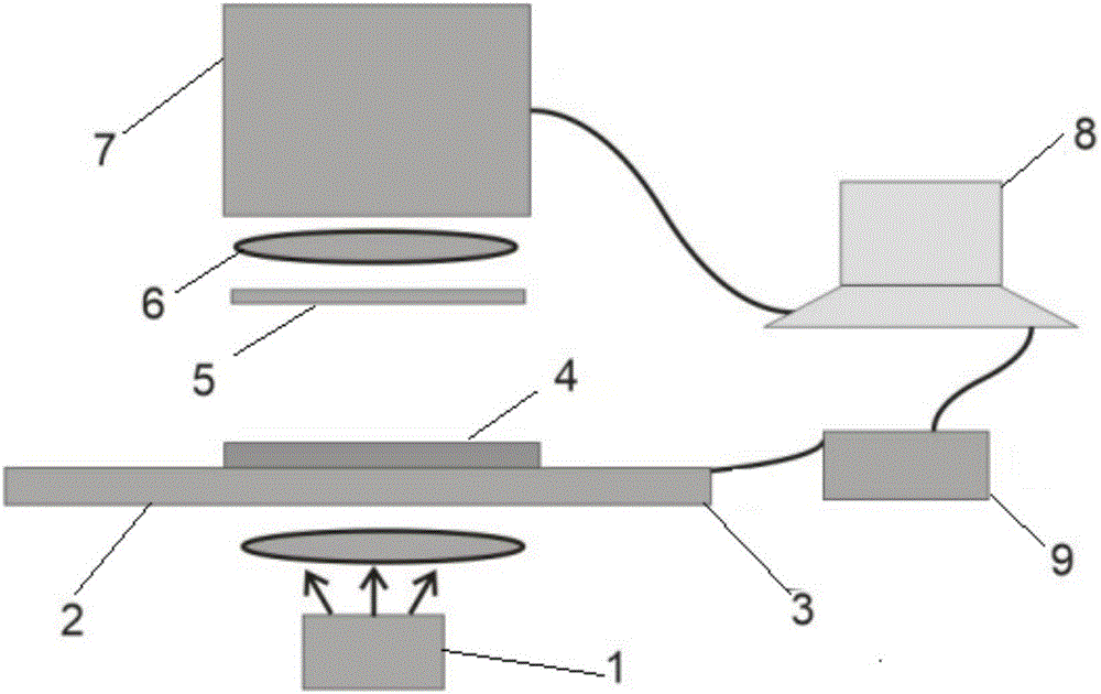
[0037] Combine below figure 1 Be explained. Detect unstained tissue sections to assist in judging cancerous tissues and their borders. At this time, the wavelength of the push-broom imaging spectrometer used is a near-infrared imaging spectrometer. The wide-spectrum light source 1 is focused on the slice of the tissue sample 4 to be tested through the objective lens or the lens 2 , and the slice of the sample 4 to be tested is fixed on the translation stage 3 . The one-dimensional scanning of the slice of the sample 4 to be tested is realized by the movement of the displacement stage 3 . The transmitted light passes through the filter 5 and the focusing lens 6 in turn, and then enters the imaging spectrometer 7, 8 is a computer, and 9 is a drive controller of the translation stage 3. The line light source at this time is produced by focusing a broad-spectrum light source onto a slit.

[0038] The y of the sample coordinates corresponds to the y1 of the area array camera, a...

Embodiment 2

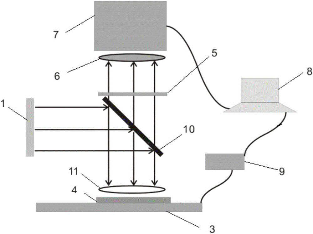
[0043] The optical path structure of the system is as figure 2 shown. figure 2 Among them, 1 is the excitation line light source, 3 is the translation stage, 4 is the sample to be tested, 5 is the filter, 6 is the focusing lens, 7 is the imaging spectrometer, 9 is the controller of the translation stage, 8 is the computer, and 10 is the two-way The color mirror, 11 is a lens, and the computer controls the data acquisition of the imaging spectrometer and the movement of the displacement stage. The light emitted by the line light source 1 is reflected by the dichroic mirror 10 , and then focused on the slice of the sample 4 to be measured by the lens 11 . The sample 4 to be tested is fixed on the displacement stage 3, and the sample is scanned by controlling the movement of the displacement stage 3; the signal radiated by the sample passes through the focusing lens 11, the dichroic mirror 10, the filter 5, the focusing lens 6, and the focusing into a pushbroom imaging spectr...


PUM


Abstract

The invention discloses a line light source excitation-based rapid high-throughput hyperspectral detection device and a detection method. The detection device comprises a light source, an objective lens or lens, a displacement stage, a filter plate, a focusing lens and an imaging spectrometer. A sample to be measured is placed on the displacement stage; light emitted from the light source successively passes through the objective lens or lens, the displacement stage and the sample to be measured; and light that the sample to be measured radiates passes through the filter plate and the focusing lens and then enters the imaging spectrometer. By illuminating the sample through the light source, scanning the sample through the displacement stage and acquiring spectral signals that the sample radiates through the imaging spectrometer, spectrum and spatial position information of the sample can be obtained rapidly. By the active lighting mode, signal to noise ratio of the system is high, and quantitative detection of an object can be realized.

Description

technical field [0001] The invention belongs to the field of hyperspectral detection, and in particular relates to a hyperspectral detection and analysis device and method based on a line light source, a push-broom imaging spectrometer, and a precision displacement platform. Background technique [0002] The imaging spectrometer was proposed by the Jet Propulsion Laboratory of the United States in the 1980s. On the basis of the spectrometer, imaging technology was added, which changed the shortcomings of traditional detection instruments that can only obtain a single information of the measured target, and can obtain the spectral information of the object. and spatial distribution information. According to different scanning methods, imaging spectrometers can be divided into three types: swing-broom, push-broom, and staring. The swing-broom imaging spectrometer scans with a mechanical structure in the x direction, and completes the scan with the movement of the device on th...

Claims


Application Information

Patent Timeline
IPC IPC(8): G01N21/01G01N21/63
CPCG01N21/01G01N21/63
Inventor 何赛灵李静伟
Owner SUZHOU YOUHAN INFORMATION TECH CO LTD
Why Eureka
Try Eureka