Adjustable two bulb lamp adapter

a technology of adapter and bulb, which is applied in the direction of lighting support devices, coupling device connections, lighting and heating apparatuses, etc., can solve the problem of not being supplied with the necessary mechanism to adjust the adapter, and achieve the effect of ensuring the rotational resistan

Active Publication Date: 2017-04-25
BARRY PAUL ABELL
View PDF4 Cites 4 Cited by
  • Summary
  • Abstract
  • Description
  • Claims
  • Application Information

AI Technical Summary

Benefits of technology

[0003]1. A two bulb holder lamp adapter with each holder separated for independent rotation, closely positioned near the male screw base and with electrical connections to allow each bulb holder limited rotation in a plane parallel or nearly parallel to the axis of the adapter base threads. With the invention positioned in a normal upright attitude, this feature allows each of the two bulb holders to be independently rotated to positions from vertical to below horizontal to achieve optimum distribution of lighting effects from the two bulbs and to be positioned if necessary to avoid possible interferences to any original lamp hardware. The invention adapter may be installed in any position corresponding to the required positioning of the receiving bulb socket. This provision will also permit positioning of each bulb to achieve optimum clearance between an existing shade and the bulb for heat related safety concerns.
[0006]4. The provision of a spring loaded device on the supporting mechanism of the rotatable bulb holder is incorporated to offer adequate rotational resistance to allow each bulb holder to be adjusted to position without the need for an added locking-unlocking device to be operated by the user installer.

Problems solved by technology

Other two bulb adapters are available however mechanisms are not being supplied to adjust the adapter to the three-way switching means in the widely used four position switched lamp holder.

Method used


Image

  • Adjustable two bulb lamp adapter
  • Adjustable two bulb lamp adapter
  • Adjustable two bulb lamp adapter

Examples


Embodiment Construction

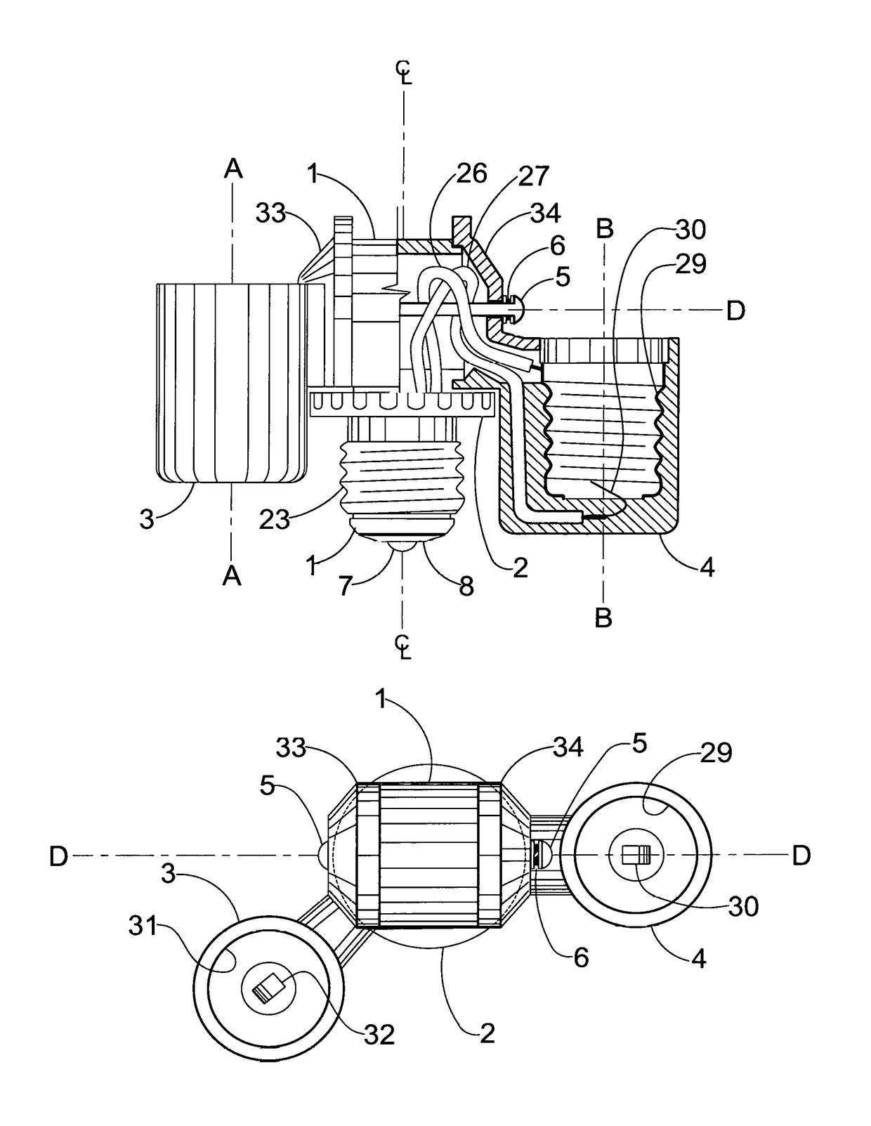
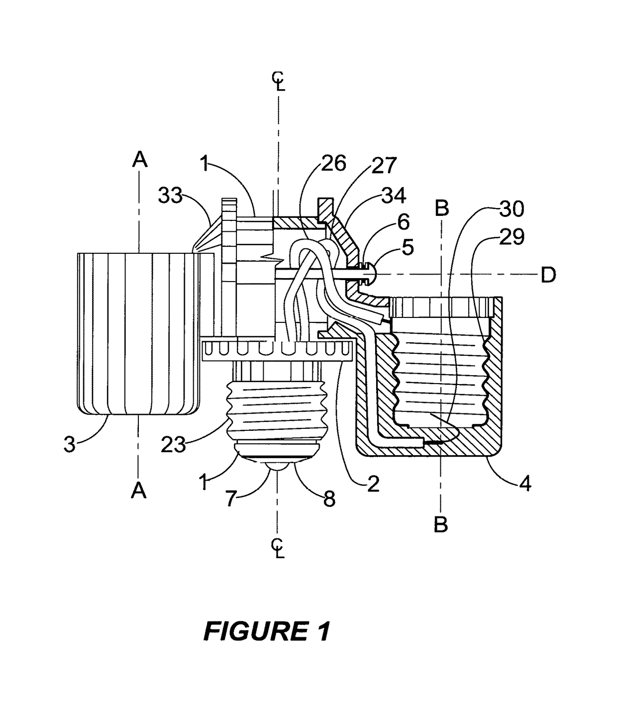
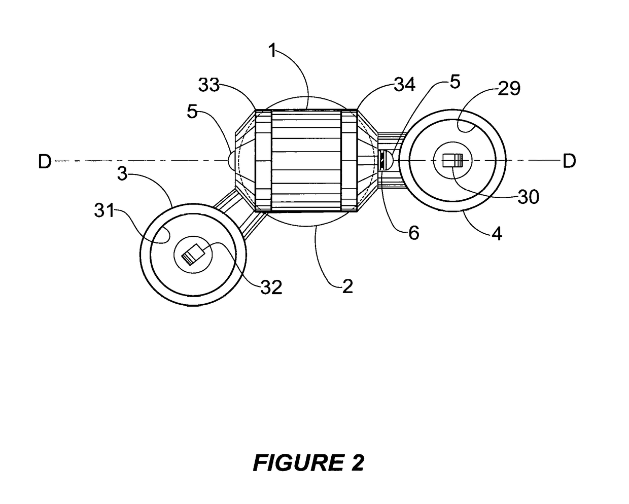
[0016]Refer to FIGS. 1, 2 and 3. The adjustable two bulb lamp adapter consists of the main components comprising the body 1, cylindrical element 2 with attached screw shell 23 (which is the major portion of a three way light bulb base) and two bulb holders 3 and 4 each constructed of a suitable material having sufficient strength, endurance and electrical insulating properties to safely support metal conductors, light bulbs and metal connecting parts. The subject adjustable two bulb lamp adapter will be referred to as the adapter or the adjustable two bulb lamp adapter in the following specifications.

[0017]Refer to FIG. 1. FIG. 1 displays the adjustable two bulb lamp adapter in a front view with a cross sectional view of bulb holder 4 and a partial cross sectional view of the upper portion of body 1 included. The two bulb holders 3 and 4 are held in contact with body 1 by pivot rod 5. Pivot rod 5 provides a shaft about which socket holders 3 and 4 can rotate within preset limits. Th...


PUM


Abstract

This adjustable two bulb lamp adapter is an electrical device with a male threaded light bulb type base to permit use of two low energy CFL bulbs in place of and function as a three-way incandescent light bulb in existing shade lamps. The adapter embodies two bulb holders with limited and independent rotational adjustment in a plane parallel to the axis of the threaded base. An integral thumb wheel permits rotating and securing the adapter base into the receiving socket while the two bulbs are held in a fixed position. An included adjuster allows utilization as a two bulb adapter for a single filament bulb type socket. These adjustments provide means to optimize fit and light distribution in existing lamp shades and other applications. The concept of using the adapter's adjustable two bulb sockets greatly enhances selecting lower energy CFL bulbs to achieve higher levels of illumination in more applications than available in fixed adapters.

Description

[0001]This application claims priority from U.S. Provisional application No. 61 / 998,469 filed on Jun. 30, 2014BACKGROUND[0002]This invention fills the need for an adapter to provide to the ubiquitous three-way incandescent lamp holder a means to allow replacement of a two filament incandescent electric light bulb with an electrical device containing two separate adjustable light bulb holders permitting continued use of the existing four position switching mechanism to function as a three-way lamp holder. The higher energy consumption of the three-way incandescent light bulb can be replaced by two energy efficient Compact Fluorescent Light (CFL) bulbs with the same three-way functioning and thus eliminate the need to replace the higher cost three-way CFL if one level fails. Other two bulb adapters are available however mechanisms are not being supplied to adjust the adapter to the three-way switching means in the widely used four position switched lamp holder. This invention can also...

Claims


Application Information

Patent Timeline
Patent Type & Authority Patents(United States)
IPC IPC(8): F21V19/02F21V19/00F21V21/30H01R33/90
CPCF21V19/02F21V19/0065F21V21/30H01R33/90
Inventor BARRY, PAUL ABELL
Owner BARRY PAUL ABELL
Why Eureka
Try Eureka