Ink temperature adjustment device and ink circulation type inkjet printer having the same

a technology of ink circulation type and temperature adjustment device, which is applied in printing and other directions, can solve problems such as abnormal ink ejection, and achieve the effects of increasing the heat exchange ratio along the path surface, increasing the effective temperature adjustment, and increasing the speed of ink flow

Active Publication Date: 2017-05-02
RISO KAGAKU CORP
View PDF18 Cites 0 Cited by
  • Summary
  • Abstract
  • Description
  • Claims
  • Application Information

AI Technical Summary

Benefits of technology

[0009]It is an object of the present invention to provide an ink temperature adjustment device and an ink circulation type inkjet printer which are capable of efficiently adjusting the temperature of ink by increasing the length of an ink path in the ink circulation type inkjet printer and, at the same time, reducing air bubbles remaining in the path to prevent the occurrence of abnormal ink ejection at an ink head.
[0012]According to the above configuration, the total cross-sectional area of the downflow path is made smaller than that of the upflow path. In this way, the speed of the ink flow can be increased, thereby making it possible to reduce air bubbles generated and remaining in the ink at bent portions and branching points on the flow path and to supply the ink smoothly. On the other hand, as for the upflow path, the flow path may be branched or the diameter thereof may be increased, for example, so that the cross-sectional area of the flow path can be increased. In this way, the heat exchange ratio along the path surface can be increased and effective temperature adjustment can therefore be achieved.
[0013]Specifically, in an upflow path, air bubbles are also directed upward by their buoyancy. Then, with the presence of the ink flow, the air bubbles are less likely to remain in the flow path. In the above configuration, by taking advantage of this condition, the upflow path is, for example, branched or bent so that the surface area thereof can be increased. In this way, the heat exchange ratio is increased and, even if air bubbles are generated, the air bubbles will flow naturally upward through the upflow path and will therefore not remain therein. On the other hand, in a downflow path, air bubbles are directed upward by their buoyancy whereas the ink flow is directed downward, so that the air bubbles move against the ink flow. Thus, the air bubbles are more likely to remain at bent portions and branching points on the flow path. In view of this, in the above configuration, the total cross-sectional area of the downflow path is made smaller, for example. In this way, the speed of the ink flow increases, thereby making it possible to push out accumulated air bubbles and smoothly supply the ink without allowing the air bubbles to remain. Hence, it is possible to make the temperature adjustment more efficient and to reduce residual air bubbles at the same time.
[0015]According to the above configuration, the upflow path is divided into the first upflow path on the inlet path side and the second upflow path on the outlet path side, and they are connected by the downflow path therebetween. In this way, for example, the first upflow path can be arranged for cooling and the second upflow path can be arranged for heating, and the ink temperature adjustment path can be made compact as well. This makes it possible to achieve size reduction of the device as a whole and space saving.
[0017]According to the above configuration, the total the number of the second flow paths branched in the second upflow path and the downflow path is equal to the number of the first flow paths branched in the first upflow path. In this way, the symmetry of the ink temperature adjustment path can be maintained, and the ink temperature adjustment path can therefore be designed symmetrically between the heating side and the cooling side, for example. This makes it possible to simplify the temperature control and also avoid complication of the device.
[0020]According to the above configuration, by increasing the total surface area of the upflow path, the heat exchange ratio along the path surface is increased and effective temperature adjustment is therefore achieved; on the other hand, by making the surface area of the downflow path smaller than that of the upflow path, the speed of the ink flow is increased, thereby making it possible to reduce air bubbles remaining in the ink and to supply the ink smoothly to the inkjet head. In this way, images can be formed on a recording medium with high accuracy. Hence, the image quality and the print rate can be improved.

Problems solved by technology

However, with a meandering ink path, there is a possibility that air bubbles remain at the bent portions when the ink is initially filled and that these air bubbles flow into the head and cause abnormal ink ejection.

Method used


Image

  • Ink temperature adjustment device and ink circulation type inkjet printer having the same
  • Ink temperature adjustment device and ink circulation type inkjet printer having the same
  • Ink temperature adjustment device and ink circulation type inkjet printer having the same

Examples


Embodiment Construction

[0030]In the following detailed description, for purposes of explanation, numerous specific details are set forth in order to provide a thorough understanding of the disclosed embodiments. It will be apparent, however, that one or more embodiments may be practiced without these specific details. In other instances, well-known structures and devices are schematically shown in order to simplify the drawing.

[0031]Description will be hereinbelow provided for an embodiment of the present invention by referring to the drawings. It should be noted that the same or similar parts and components throughout the drawings will be denoted by the same or similar reference signs, and that descriptions for such parts and components will be omitted or simplified. In addition, it should be noted that the drawings are schematic and therefore different from the actual ones.

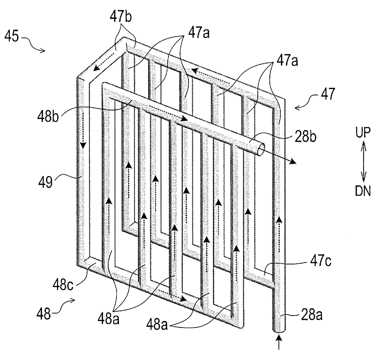
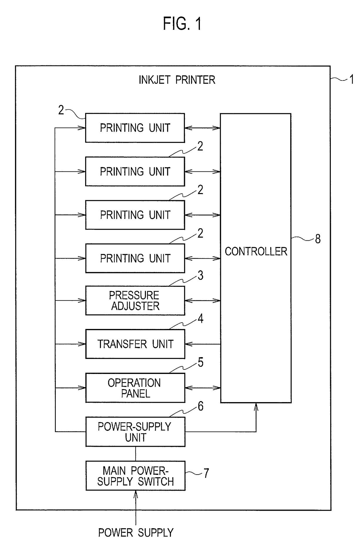
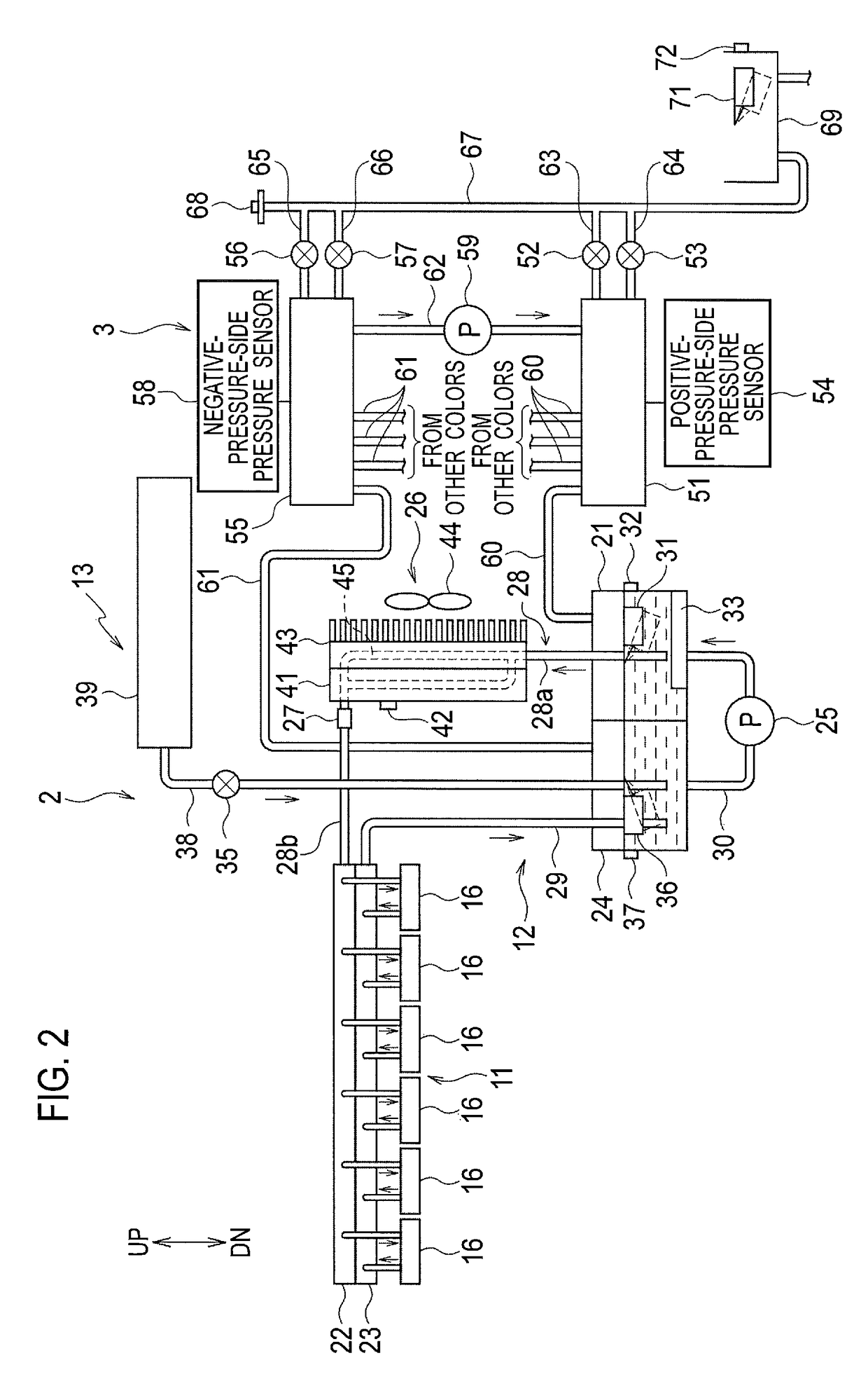
[0032]FIG. 1 is a block diagram showing the configuration of an inkjet printer according to an embodiment of the present invention. ...


PUM


Abstract

An ink temperature adjustment device and an inkjet printer include an ink temperature adjustment path connected to a midway point on an ink supply path for supplying ink to an inkjet head configured to form an image by ejecting the ink. The ink temperature adjustment path is for adjusting a temperature of the ink supplied to the inkjet head. The ink temperature adjustment path includes an upflow path for the ink to flow upward and a downflow path for the ink to flow downward. A total cross-sectional area of the upflow path is larger than a total cross-sectional area of the downflow path.

Description

CROSS REFERENCE TO RELATED APPLICATION[0001]This application is based upon and claims the benefit of priority from the prior Japanese Patent Application No. 2014-173886, filed on Aug. 28, 2014, the entire contents of which are incorporated herein by reference.BACKGROUND[0002]1. Technical Field[0003]The disclosure relates to an ink temperature adjustment device and an ink circulation type inkjet printer which are configured to adjust the temperature of ink to be supplied to an inkjet head configured to form an image by ejecting the ink.[0004]2. Related Art[0005]An ink circulation type inkjet printer has been known which is configured to perform printing by ejecting ink from an inkjet head while circulating the ink. Japanese Unexamined Patent Application Publication No. 2012-153004 describes an ink circulation type inkjet printer including a positive-pressure tank and a negative-pressure tank arranged below an inkjet head, and an air pump configured to send air from the negative-press...

Claims


Application Information

Patent Timeline
Patent Type & Authority Patents(United States)
IPC IPC(8): B41J2/175B41J2/195
CPCB41J2/175B41J2/195
Inventor AKIYAMA, TOMOYUKISHIMODA, ASAYOSUGITANI, HIROSHINISHIYAMA, AKIRA
Owner RISO KAGAKU CORP
Why Eureka
Try Eureka