Panel joint structure

a panel joint and joint technology, applied in the direction of superstructure connections, superstructure subunits, vehicle components, etc., can solve the problems of increasing the distance between the pair of beads, and the inability to seal the air passageway by the seal member, so as to improve the formability of the first panel, enhance the air venting effect of the distal end portion of the first panel bead portion, and improve the workability of disposing the seal member on the distal end portion of the first panel b

Active Publication Date: 2017-05-09
TOYOTA JIDOSHA KK
View PDF9 Cites 6 Cited by
  • Summary
  • Abstract
  • Description
  • Claims
  • Application Information

AI Technical Summary

Benefits of technology

[0009]In view of the circumstances described above, it is an object of the present invention to provide a panel joint structure that can ensure sealedness and joint strength between a first panel and a second panel and can enhance the air venting effect resulting from an air vent hole.

Problems solved by technology

However, in this case, the distance between the pair of beads increases, so the air passageway can no longer be sealed by the seal member at the distal end portions of the pair of beads.

Method used


Image

  • Panel joint structure
  • Panel joint structure
  • Panel joint structure

Examples


Embodiment Construction

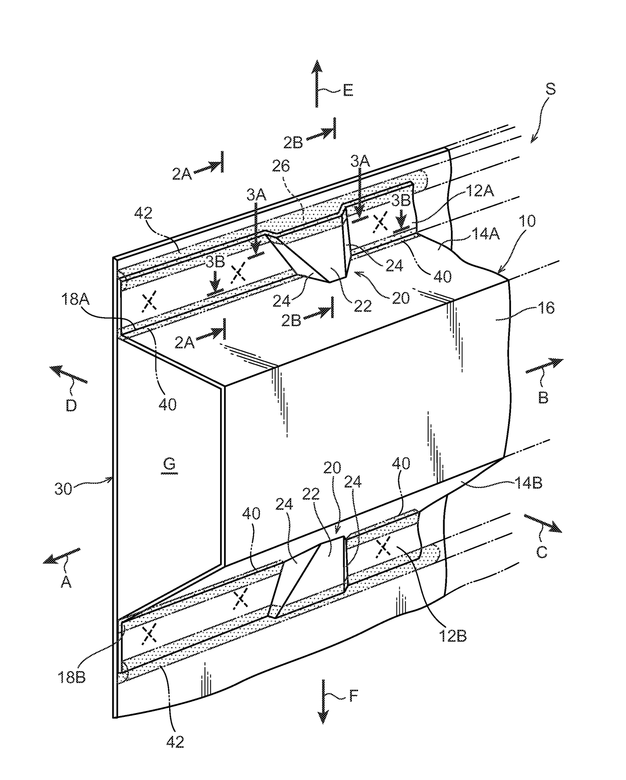
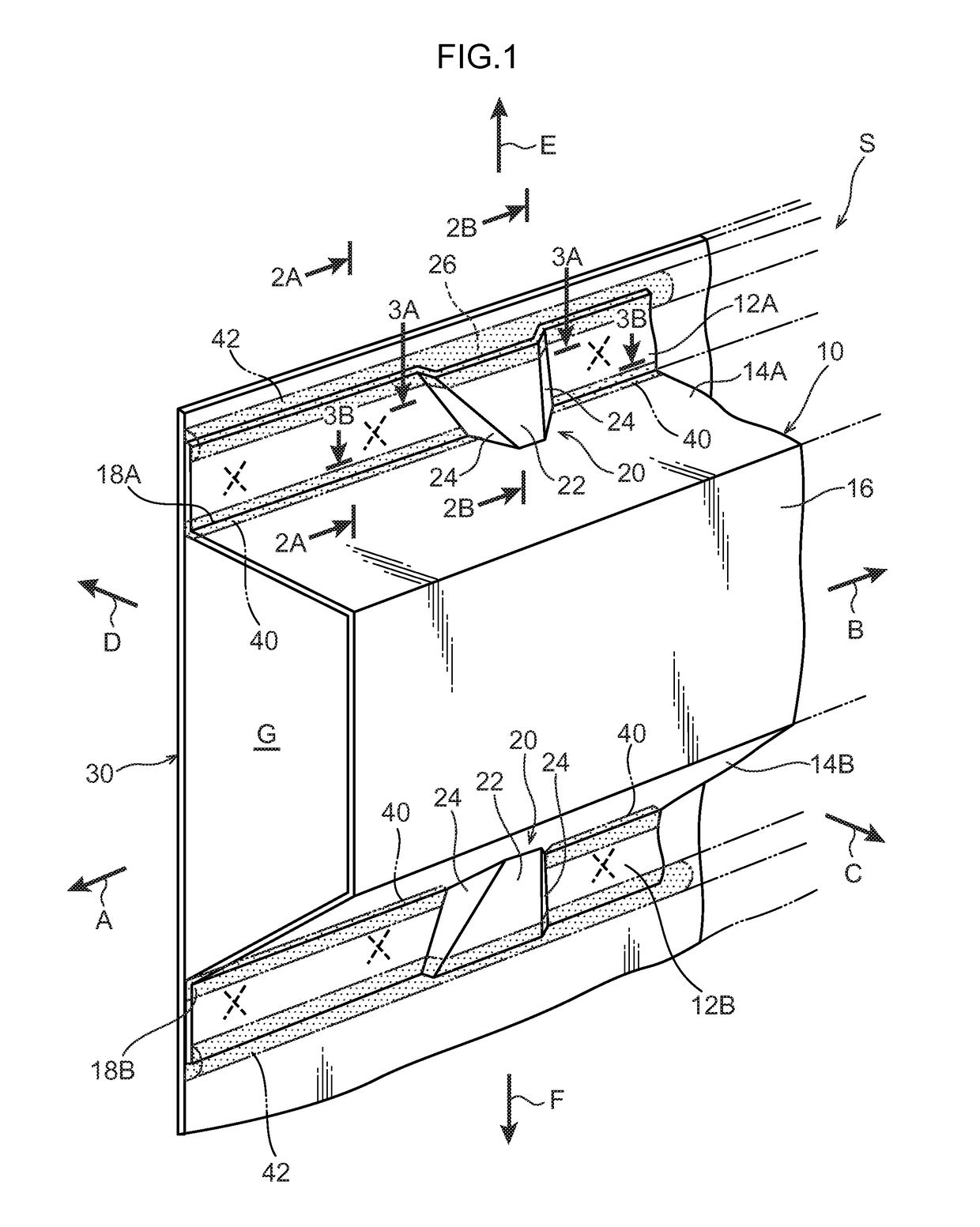
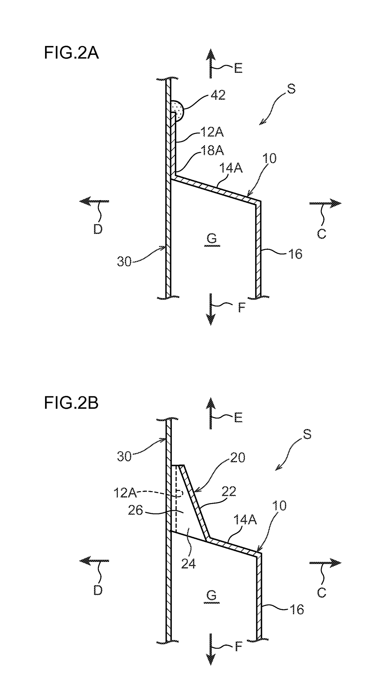
[0057]A panel joint structure S pertaining to an embodiment of the present invention will be described below using the drawings. As shown in FIG. 1, the panel joint structure S is applied to joint sections between a first panel 10 and a second panel 30. Additionally, the first panel 10 and the second panel 30 are members that configure the lower portion of a vehicle (automobile). That is, the first panel 10 is, for example, a skeletal member such as a cross member whose lengthwise direction coincides with the vehicle width direction of the vehicle or a side member whose lengthwise direction coincides with the front and rear direction of the vehicle, and the second panel 30 is, for example, a floor panel that configures the floor of the vehicle. These will be specifically described below.

[0058]The first panel 10 is configured by a steel plate and is formed in a substantially elongated shape along the direction of arrow A and the direction of arrow B in FIG. 1. Furthermore, the first ...


PUM


Abstract

A panel joint structure including: a first panel; a second panel that forms a space between itself and the first panel; a joint portion; a seal member that seals a gap between a distal end portion of the joint flange portion and the second panel; and a first panel bead portion that is formed in a region of the joint flange portion adjacent to the joint portion in the lengthwise direction of the first panel, that projects in a direction away from the second panel, that extends from a distal end to a base end of the joint flange portion, that forms with the second panel an air vent hole communicated with the space, and that slopes in a direction away from the second panel heading toward the base end side of the joint flange portion as seen from the lengthwise direction of the first panel.

Description

CROSS-REFERENCE TO RELATED APPLICATION[0001]This application is based on and claims priority under 35 USC 119 from Japanese Patent Application No. 2014-193691 filed on Sep. 24, 2014, the disclosure of which is incorporated by reference herein.BACKGROUND[0002]Technical Field[0003]The present invention relates to a panel joint structure.[0004]Related Art[0005]Japanese Patent Application Laid-open (JP-A) No. 2013-136076 discloses a panel joint structure wherein a pair of panels each have a flange and the flanges are joined to one another. Furthermore, a cross-sectionally substantially semicircular shaped bead is formed in each of the pair of flanges, and an air passageway (air vent hole) is formed by the pair of beads. Because of this, when the pair of panels are electrodeposition coated in a state in which the panels have been joined to one another, air between the pair of panels can be vented from the air passageway.[0006]Furthermore, after the electrodeposition coating of the panels...

Claims


Application Information

Patent Timeline
Patent Type & Authority Patents(United States)
IPC IPC(8): B62D25/24B62D27/02B62D25/08B62D25/02
CPCB62D25/24B62D25/02B62D25/082B62D27/02
Inventor KOSAKA, NAOYA
Owner TOYOTA JIDOSHA KK
Why Eureka
Try Eureka