Cap for container

a container and cap technology, applied in the field of caps, can solve the problems of cap becoming no longer reusable, easy to drop the separated cap, accidental disposal, misplacement/lost, etc., and achieve the effect of simple design and structur

Active Publication Date: 2017-05-09
THISCAP INC
View PDF16 Cites 15 Cited by
  • Summary
  • Abstract
  • Description
  • Claims
  • Application Information

AI Technical Summary

Benefits of technology

[0008]The object of the present invention is to provide a cap for a container. More particularly, compared to conventional caps, the cap provided by the present invention, through its much simpler design and structure, will allow the cap in an open state relative to its container to still be maintained in a connected state to the container. In addition, the cap of the present invention will also remain in an open state, when so desired, without any physical manipulation from the user. The cap will not interfere with the opening of the container while in an open state and the free movement of the cap will be limited preventing the cap, while in the open state, from interfering with the user. The cap of the present invention can quite easily be returned to the closed sealed state and will also prevent the cap from being dropped, lost, misplaced, accidentally discarded, soiled by contact with uncontrolled surfaces or allowed to pollute, damage or adversely affect the environment.
[0017]In the present invention, the outer side of the main body of the cap provided can have a knurled portion. When the container is to be opened, the knurled portion can facilitate applying a force to rotate and separate the main body and the ring member.
[0018]In the present invention, depending on the actual needs, the first incision line disposed between the main body and the ring member of the cap provided can have a plurality of connecting pins to connect the main body and the ring member. The shape, size, quantity, and spacing of the plurality of connecting pins are not particularly limited. When the size and quantity of the plurality of connecting pins of the first incision line are smaller and the spacing of the plurality of connecting pins is larger, the force needed to break the plurality of connecting pins is smaller. Subsequently, the separation of the main body and the ring member will be easier. On the contrary, when the size and quantity of the plurality of connecting pins of the first incision line are larger and the spacing of the plurality of connecting pins is smaller, the force needed to break the plurality of connecting pins is larger. Subsequently, the separation of the main body and the ring member will be more difficult. In the cap provided by the present invention, the plurality of second incision lines do not possess a plurality of connecting pins.
[0019]In the present invention, when the main body of the cap provided by the present invention has been screwed opened from the opening of the container, the plurality of connecting portions will connect the main body and the ring member together. Since the ring member is fitted below a bulge portion of the opening of the container; thus, the ring member will not detach from the opening of the container. As a result, the connection between the main body separated from the opening of the container with the ring member will allow the main body to still remain in a connected state with the container. Moreover, the plurality of connecting portions can also allow the main body to remain in an opened state. The plurality of connecting portions will prevent the main body from interfering the opening of the container. The plurality of connecting portions will also decrease the free movement of the main body. As a result, when emptying the contents from the container, the plurality of connecting portions can prevent the main body from touching other objects due to its free movement. The residual contents at the inner side of the main body will also not be able to spill out easily. And since the ring member fitted on the opening of the container can freely rotate; hence, the plurality of connecting portions will not be pulled off easily.
[0021]Overall, in the present invention, by using the above-mentioned simple design and structure, a cap placed in an open state relative to its container will continue to be connected to its container. The cap of the present invention will also remain in an open state, when so desired, without any physical manipulation from the user. The cap will not interfere with the opening of the container while in an open state and the free movement of the cap will be limited preventing the cap, in the open state, from interfering with the user. The cap of the present invention can quite easily be returned to the closed state and will also prevent the cap from being dropped, lost, misplaced, accidentally discarded, soiled by contact with uncontrolled surfaces or allowed to pollute, damage or adversely affect the environment.

Problems solved by technology

For that reason, it is easy for the separated cap to be dropped, accidentally disposed of, and / or misplaced / lost.
Moreover, the separated cap when dropped can easily become soiled by coming in to contact with the ground or other uncontrolled surfaces resulting in the cap becoming no longer reusable.
Furthermore, the discarded or misplaced / lost separated caps are able to and will pollute the environment and cause additional environmental problems.
Nonetheless, the currently existing caps with the above-mentioned functions usually require much more complex designs.
Specifically, these designs normally involve the need of more than one component or structure; for example, besides a main body structure for the caps, the designs also necessitate a complicated connecting structure to connect the caps to their containers once the containers have been opened.
Additionally, the complicated connecting structures necessitate some difficult physical manipulation by the user to return the caps to a closed sealed state.
Accordingly, not only the cost of material increases but also the overhead costs of manufacturing equipment and man hours involved are increased as well.
The cost and inefficiency of the manufacturing process of these caps is quite high and above the market and industry requirements.

Method used


Image

  • Cap for container
  • Cap for container
  • Cap for container

Examples


example 1

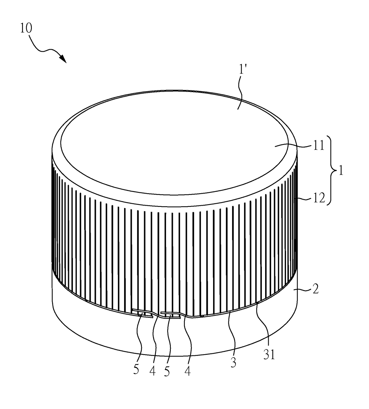
[0026]FIG. 1 is a three-dimensional schematic diagram showing an embodiment of the cap for a container of the present invention. As FIG. 1 shows, the cap 10 of the present example includes a main body 1 having a top plate 11 and a circular sidewall 12. The two opposite sides of the circular sidewall 12 circularly connect to each other. One periphery of the circular sidewall 12 connects to one surface of the top plate 11 forming a closed end 1′. The other periphery of the circular sidewall 12 at the opposite side of the closed end 1′ forms an opened end 1″ (shown in FIG. 3). The cap 10 of the present example also contains a ring member 2, which is located at the opened end 1″ of the main body 1. The ring member 2 is separated from the main body 1 by a first incision line 3 located in between the opened end 1″ of the main body 1 and the ring member 2. The first incision line 3 possesses a plurality of connecting pins 31. The plurality of connecting pins 31 located along the first inci...

example 2

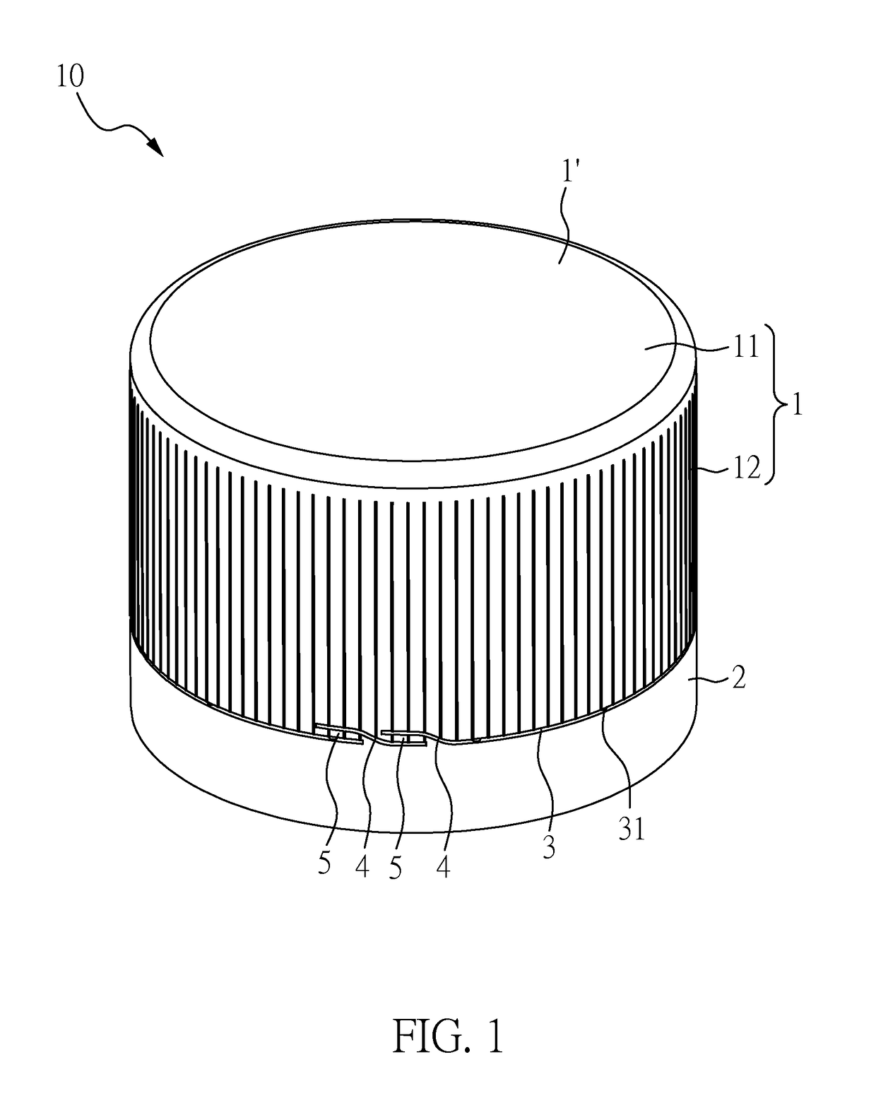
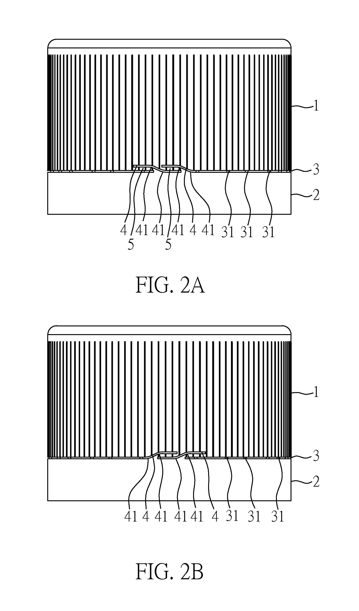
[0031]FIG. 2B is a schematic diagram showing another embodiment of the cap for a container of the present invention. The cap of the present example and the cap of example 1 are the same except that the plurality of second incision lines 4 and the plurality of second incision lines 4 shown in FIG. 2A are opposite to each other. Nevertheless, the opening directions of the cap and that of the cap shown in FIG. 2A are still the same (both are in the anti-clockwise direction; that is rotation in the right direction in FIG. 2A or FIG. 2B).

example 3

[0032]FIG. 2C is a schematic diagram showing another embodiment of the cap for a container of the present invention. The cap of the present example and the cap of example 1 are the same except that only the ring member 2 possesses the plurality of second incision lines 4 and the plurality of second incision lines 4 surround less than ⅕ of the ring member 2.


PUM

PropertyMeasurementUnit
shapeaaaaaaaaaa
lengthsaaaaaaaaaa
lengthaaaaaaaaaa

Abstract

The present invention relates to a cap for a container. The cap comprises a main body having a top plate and a circular sidewall, wherein one periphery of the circular sidewall connects to the top plate forming a closed end, and the other periphery of the circular sidewall at the opposite side of the closed end forms an opened end; and a ring member located at the opened end of the main body, separated from the main body by a first incision line, and connected to the main body by a plurality of connecting portions, wherein a plurality of second incision lines locate on the main body or the ring member and locate at one side of the plurality of connecting portions. The cap provided by the present invention will, while in its open and / or closed state, continue to be connected to its container.

Description

CROSS REFERENCE TO RELATED APPLICATION[0001]This application claims the benefits of the Taiwan Patent Application Serial Number 104110838, filed on Apr. 2, 2015, the subject matter of which is incorporated herein by reference.BACKGROUND OF THE INVENTION[0002]1. Field of the Invention[0003]The present invention relates to a cap and, more particularly, to a cap for a container.[0004]2. Description of Related Art[0005]In general, the cap of any conventional container is always completely separated from its container once the container is opened. For that reason, it is easy for the separated cap to be dropped, accidentally disposed of, and / or misplaced / lost. Moreover, the separated cap when dropped can easily become soiled by coming in to contact with the ground or other uncontrolled surfaces resulting in the cap becoming no longer reusable. Furthermore, the discarded or misplaced / lost separated caps are able to and will pollute the environment and cause additional environmental problem...

Claims


Application Information

Patent Timeline
Patent Type & Authority Patents(United States)
IPC IPC(8): B65D55/16B65D41/34
CPCB65D55/16B65D41/3428B65D41/3447B65D41/34B26F2210/04B65D2401/30Y10T83/0596Y10T83/0333Y10T83/6667B29C45/0017B29K2023/12B29L2031/565B65D41/04
Inventor MAGUIRE, MICHAEL JOSEPH
Owner THISCAP INC
Why Eureka
Try Eureka