Directional system drilling and method

a directional system and drilling technology, applied in the direction of drilling accessories, drilling machines and methods, directional drilling, etc., can solve the problems of time-consuming and costly process, poor hard rock earth performance, and use of expensive drill motors

Inactive Publication Date: 2017-05-23
KING FAHD UNIVERSITY OF PETROLEUM AND MINERALS +1
View PDF19 Cites 0 Cited by
  • Summary
  • Abstract
  • Description
  • Claims
  • Application Information

AI Technical Summary

Benefits of technology

[0046]In another embodiment the inclination movement of the four-motor drilling head is obtained by increasing or decreasing the speed of the bottom motor and the top motor.
[0047]In another embodiment the azimuth movement of the four-motor drilling head is obtained by decreasing or increasing the speed of the right motor and the left motor.

Problems solved by technology

One of the basic problems of a directional driller is to accurately set a specific tool face orientation.
The challenge is to properly orientate the down hole tool to steer the well bore in a desired direction.
The “whipstocking” process requires a series of separate operations including drilling of a pilot hole, reaming of the pilot hole to full gauge, and removal of the deflector, and is therefore a time consuming and costly process.
The use of “bent subs” to produce lateral forces on the drill bit requires the use of expensive drill motors; and the “side jetting” process, using special drill bits to provide offset holes by the pressurized drill mud, does not function well in hard rock earth since the conventional mud pressures will not erode the hard rock materials.
As a result, the non-uniform succession of cutting elements often imparts an abrupt impact force during rotation of the cutter.
Moreover, by design the outer surface of the cutter does not have relief grooves which initially aid in carrying away a disintegrated formation with the drilling fluid.
The method has no provision for true directional steering and is not suitable for oil drilling, as the extensions of the lateral drilling string is limited by collars that can only fit within the main hole.

Method used


Image

  • Directional system drilling and method
  • Directional system drilling and method
  • Directional system drilling and method

Examples


Embodiment Construction

[0067]Referring now to the drawings, wherein like reference numerals designate identical or corresponding parts throughout the several views.

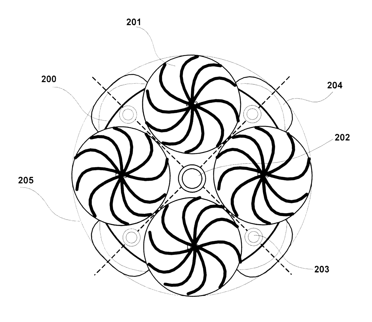
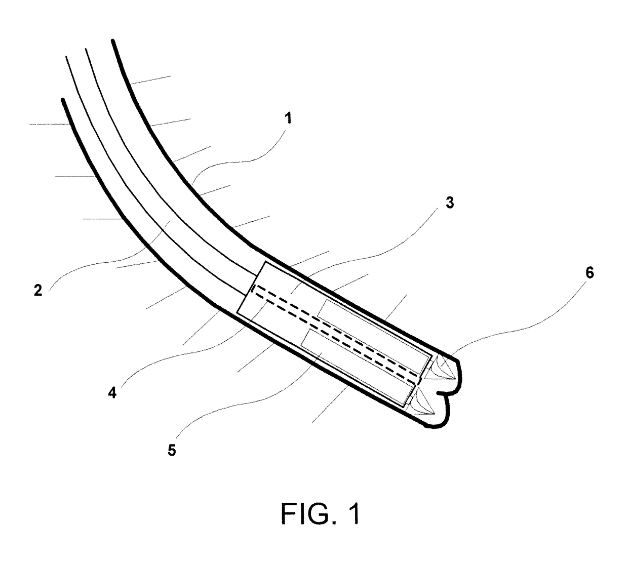
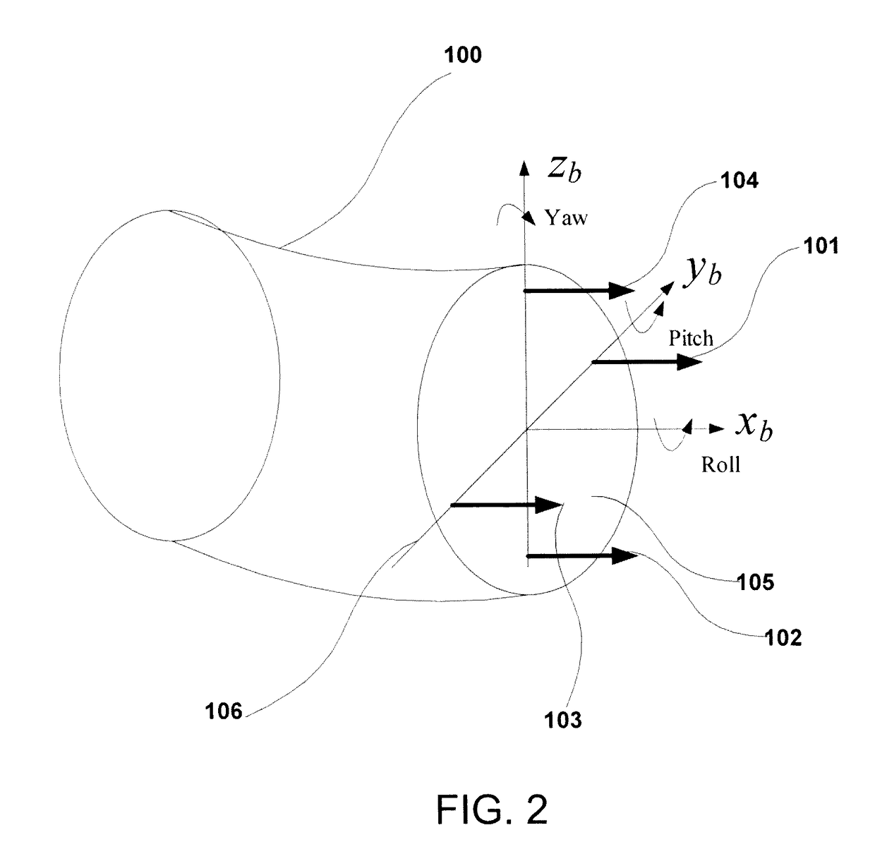
[0068]The present disclosure relates to a directional drilling system consisting of a four-motor drilling head to allow for better steering in directional drilling and vertical and horizontal drilling. The rotational speed of each motor is independently controlled. The use of four motors in coordination with other traditional drilling variables allows for precise control of the drilling direction and optimization of the rate of penetration (ROP). The top and right motors rotate in opposite directions to the bottom and left rotors to stabilize the roll rotation of the drilling head. Inclination (pitch) movement is obtained by increasing or decreasing the speed of the top motor while decreasing or increasing the speed of the bottom motor. The Azimuth (yaw) movement is obtained by increasing or decreasing the speed of the right motor while decreas...


PUM


Abstract

A directional drilling system consisting of a four-motor drilling head for better steering in directional drilling and vertical / horizontal drilling is developed. The rotational speed of each motor is independently controlled. The use of four motors in coordination with other traditional drilling variables allow precise control of the drilling direction and optimization of the rate of penetration (ROP). The top and right motors rotate in opposite directions to the bottom and left rotors to stabilize the roll rotation of the drilling head. Inclination (pitch) movement is obtained by increasing / decreasing the speed of the top motor while decreasing / increasing the speed of the lower motor. The Azimuth (yaw) movement is obtained similarly using the right and left motors. The drilling power is derived from down hole motors. A drill string transmits the drilling fluid and force on bit.

Description

BACKGROUND OF THE INVENTION[0001]Technical Field[0002]The present invention relates to a directional drilling system comprising a four-motor drilling head driving four independent bit assemblies positioned in a front face plane of the drilling head, independently controlled rotational speed mechanisms for each motor, and an inclination or azimuth controller to decrease or increase the speed of either a bottom motor, a top motor, a right motor or a left motor; and a method of drilling using the directional drilling system[0003]Description of the Related Art[0004]The “background” description provided herein is for the purpose of generally presenting the context of the disclosure. Work of the presently named inventors, to the extent it is described in this background section, as well as aspects of the description which may not otherwise qualify as prior art at the time of filing, are neither expressly or impliedly admitted as prior art against the present invention.[0005]Conventional b...

Claims


Application Information

Patent Timeline
Patent Type & Authority Patents(United States)
IPC IPC(8): E21B4/16E21B7/06E21B4/04E21B4/02
CPCE21B4/16E21B7/068E21B4/02E21B4/04
Inventor ELSHAFEI, MOUSTAFAKHOUKHI, AMARAL-MAGED, ABDULAZIZTALIB, MOHAMMAD
Owner KING FAHD UNIVERSITY OF PETROLEUM AND MINERALS
Why Eureka
Try Eureka