Band saw blade sensor and control system

a technology of a control system and a sensor, which is applied in the direction of program control, metal sawing accessories, instruments, etc., can solve the problems of blade deflection, blade deflection, and flexible blade movement or migration during, so as to reduce the set point force of the blade on the workpiece, increase the blade tension, and reduce the speed of the blad

Active Publication Date: 2018-12-11
HE&M
View PDF43 Cites 0 Cited by
  • Summary
  • Abstract
  • Description
  • Claims
  • Application Information

AI Technical Summary

Benefits of technology

[0022]In response thereto, the blade tension may be increased by increasing the distance between the drive pulley or wheel and the idle pulley or wheel. Alternatively, or in addition thereto, the set point force of the blade on the work piece may be decreased. Finally, the speed of the blade may be increased or decreased. One or more of these actions will tend to bring the blade back into alignment.

Problems solved by technology

An existing problem with continuous metal saw blades is that the flexible blade is known to move or migrate during a cutting operation for a number of reasons.
Since the backside of the blade will dull with use, the blade tends to deviate toward the opposed, sharper edge.
In addition, the blade is held in tension and therefore, when the blade is pushed too fast or with too much pressure into the material, the blade will start to deviate, resulting in deflection of the saw blade.
The system would not work when cutting ferrous metal pieces, which would interfere with the magnetic forces.
The system would only work when cutting non-ferrous materials.

Method used


Image

  • Band saw blade sensor and control system
  • Band saw blade sensor and control system
  • Band saw blade sensor and control system

Examples


Embodiment Construction

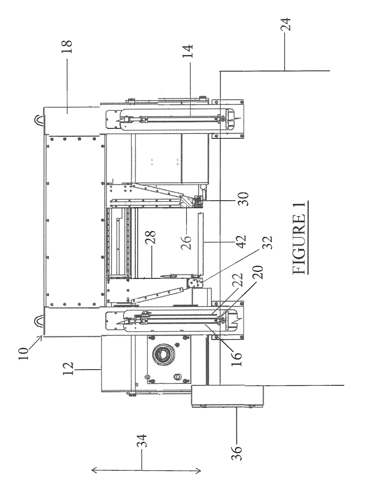
[0031]Referring to the drawings in detail, FIG. 1 illustrates a simplified diagram of a first preferred embodiment of a material cutting apparatus 10 which incorporates a band saw blade sensor and control system of the present invention. A cutting saw head 12 is supported by and moveable by a pair of arm lift cylinders 14 and 16, which are parallel to each other and are attached to a frame 18 at one end. The cutting saw head 12 remains generally parallel to the work table 24 and may be moved toward or away from the work piece (not shown) to be cut on a work table 24 The cutting saw head 12 moves in the directions shown by arrow 34. The arm lift cylinders 14 and 16 may be hydraulic or other type of cylinders within the scope of the invention.

[0032]One or both of the arm lift cylinders 14 and 16 includes a force or pressure sensor 20 which senses pressure in the hydraulic cylinder or cylinders in order to measure force applied on the work piece. Another sensor or sensors in the form o...


PUM

PropertyMeasurementUnit
lengthaaaaaaaaaa
lengthaaaaaaaaaa
flexibleaaaaaaaaaa

Abstract

A band saw blade sensor and control system to sense and control saw blade deviation of a continuous, flexible metal saw blade driven around a pair of pulleys. A pair of spaced proximity inductive sensors is positioned adjacent to a side of the saw blade in order to detect blade deviation during operation. A controller mechanism receives input from each of the pair of inductive sensors in order to control and adjust band tension on the blade, and in order to control and adjust blade force on a work piece.

Description

[0001]This application is a continuation-in-part application of U.S. patent application Ser. No. 14 / 690,873 filed Apr. 20, 2015 entitled “BAND SAW BLADE SENSOR AND CONTROL SYSTEM,” the contents of which are hereby incorporated by reference.BACKGROUND OF THE INVENTION[0002]1. Field of the Invention[0003]The present invention relates to a band saw blade sensor and control system which will sense deviation of a continuous flexible metal saw blade during a cutting operation and will automatically implement adjustments thereto. The system could further implement adjustments based on a variety of pre-selected factors.[0004]2. Prior Art[0005]One type of band saw employs a flexible, continuous metal band saw blade which circulates at high speed around a pair of pulleys, at least one of which is driven by a motor.[0006]Various types of bar material may be cut, such as large metal bars or ingots. Material to be cut may be brought to the band saw by a material handling feed table, such as show...

Claims


Application Information

Patent Timeline
Patent Type & Authority Patents(United States)
IPC IPC(8): B23D59/00G05B19/402B23D55/10
CPCB23D59/002G05B19/402B23D55/10B23D55/084
Inventor HARRIS, MAXWELL T.
Owner HE&M
Why Eureka
Try Eureka