Engagement-disengagement, suspension or steering release bearing, and motor vehicle equipped with such a release bearing

a technology of suspension or steering release and bearing, which is applied in the direction of mechanical actuators, couplings, mechanical apparatus, etc., can solve the problems of shear stress formation at the fitting, and achieve the effect of greater resistance to a separation for

Active Publication Date: 2017-05-30
AB SKF
View PDF6 Cites 0 Cited by
  • Summary
  • Abstract
  • Description
  • Claims
  • Application Information

AI Technical Summary

Benefits of technology

[0011]Owing to the invention, when a separating force, at least partially axial, is applied on the rings of the rolling bearing, the rolling bodies exert a reaction force to the separating force on the seal, which tends to push the folded down edge of the framework of the seal toward the groove arranged in the first ring. The part of the fitting comprised between the framework of the seal and the groove is therefore compressed on the one hand, and sheared on the other hand. In fact, the adherence force of the first ring on the fitting of the seal and the reaction force of the beads are two globally opposing forces, which share the part of the fitting filling the groove. This shearing of the material is even greater when the separating force applied is high. The separating force of the rings therefore results in the formation of a shear stress at the fitting. The latter being flexible, it withstands high shear stresses, which gives the release bearing a significant resistance to disassembly.

Problems solved by technology

The separating force of the rings therefore results in the formation of a shear stress at the fitting.

Method used


Image

  • Engagement-disengagement, suspension or steering release bearing, and motor vehicle equipped with such a release bearing
  • Engagement-disengagement, suspension or steering release bearing, and motor vehicle equipped with such a release bearing
  • Engagement-disengagement, suspension or steering release bearing, and motor vehicle equipped with such a release bearing

Examples


Embodiment Construction

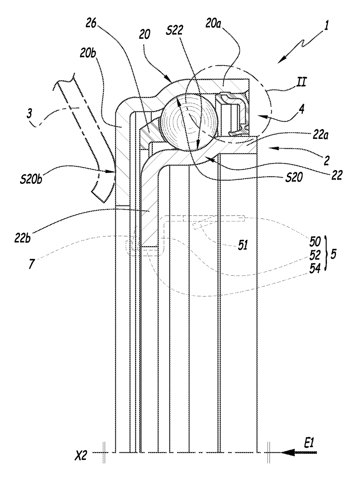
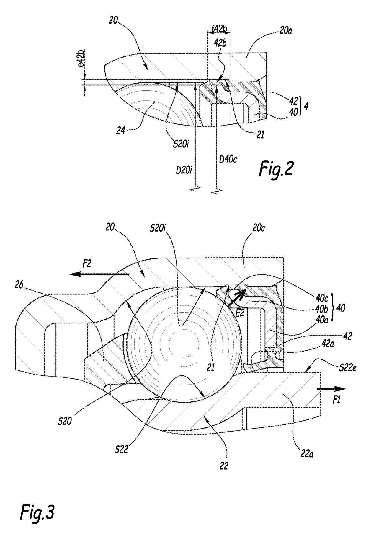
[0027]FIGS. 1 to 4 show an engagement-disengagement release bearing 1. This release bearing is designed to be mounted in a motor vehicle to transmit an axial force E1 exerted by a piston, not shown, toward a rotating transmission diaphragm, a nose 3 of which is shown in FIG. 1. In the example of FIG. 1, the diaphragm bears directly against the ring 20 on the left side of FIG. 1, but a wearing ring may also be inserted between the noses 3 and the ring 20.

[0028]The release bearing 1 comprises a rolling bearing 2 having a rotating outer ring 20 secured in rotation with the diaphragm and a non-rotating inner ring 22 between which a rolling chamber is defined. A single series of rolling bodies 24 is positioned in the rolling chamber, while being kept in position by a cage 26. In the example of the figures, the rolling bodies 24 are beads, but they may be needles or rollers.

[0029]Reference X2 denotes a central axis of the rolling bearing 2, i.e., the relative axis of rotation of the rings...


PUM


Abstract

An engagement-disengagement, suspension or steering release bearing. The release bearing includes a rolling bearing forming a member for transmitting an axial force and comprising a rotating ring and a non-rotating ring between which a rolling chamber is mounted for rolling bodies and a sealing gasket, which is mounted on a first ring among the rotating and non-rotating rings, and which comprises a framework, having an edge folded down radially toward a groove arranged on a surface of the first ring, and a fitting, having a sealing lip in sliding bearing against, or adjacent to, a corresponding surface of the second ring, The fitting of the seal is suitable for filling the groove of the first ring and part of the fitting is jammed between the folded down edge of the framework and the groove in the configuration with the seal mounted on the first ring.

Description

CROSS REFERENCE TO RELATED APPLICATIONS[0001]This is a Non-Provisional Patent Application, filed under the Paris Convention, claiming the benefit of French Patent (FR) Application Number 1456877, filed on 17 Jul. 2014, which is incorporated herein by reference in its entirety.TECHNICAL FIELD[0002]The invention relates to an engagement-disengagement, suspension or steering release bearing used in a motor vehicle to transmit an axial force between a non-rotating part, such as an actuating piston, and a rotating part, such as the noses of a transmission diaphragm.BACKGROUND ART[0003]In the automobile industry, it is known to use an engagement-disengagement release bearing to actuate the rotating diaphragm of a transmission from a translatable piston. To that end, the release bearing comprises a rolling bearing with rolling bodies, with a rotating ring designed to be in contact with the noses of the diaphragm, and a non-rotating ring that defines a central opening in which a maneuvering...

Claims


Application Information

Patent Timeline
Patent Type & Authority Patents(United States)
IPC IPC(8): F16C33/76F16C19/16F16D23/14F16C33/78
CPCF16C33/761F16C19/163F16C33/78F16C33/7826F16C33/7856F16D23/14F16C2361/43F16D2300/08F16C33/768F16C33/783F16C33/7876
Inventor ARNAULT, BENOIT
Owner AB SKF
Why Eureka
Try Eureka