
Adaptive colorspace conversion for 3D stereoscopic disparity estimation

a colorspace and disparity estimation technology, applied in the field of stereoscopic disparity estimation, can solve the problems of time-consuming and complex hardware, and achieve the effect of improving disparity estimation and improving disparity estimation

Active Publication Date: 2017-05-30
SONY CORP
View PDF11 Cites 0 Cited by
  • Summary
  • Abstract
  • Description
  • Claims
  • Application Information

AI Technical Summary

Benefits of technology

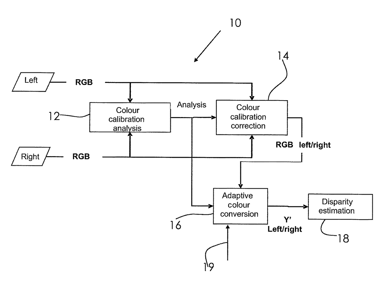
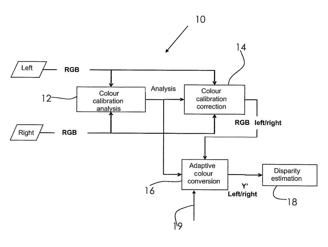
This approach improves the disparity estimation process by generating a single channel with increased information content, reducing computational complexity and enhancing the accuracy of depth information calculation, while leveraging existing color calibration modules for low implementation effort.

Problems solved by technology

However, this requires complex hardware, e.g. large memory for storing all channels, and is time consuming.

Method used


Image

  • Adaptive colorspace conversion for 3D stereoscopic disparity estimation
  • Adaptive colorspace conversion for 3D stereoscopic disparity estimation

Examples


Embodiment Construction

[0017]3D stereoscopic devices, like TV sets, beamers, laptops, notebooks, personal computers, tablet computer, etc. have the capability to display 3D video content that consists of two image sequences, one for the left eye and the other for the right eye. The pixel-by-pixel displacement between the left and right eye images, called disparity, is directly related to the depth of the objects that the user perceives. Such 3D stereoscopic devices comprise circuitry for disparity estimation and / or to calculate disparity maps. Disparity maps, for example, are used to place text or graphic into 3D scenes, to generate new views or to adjust the depth of the scenes and objects to meet the viewer's comfort level. For example, when watching stereoscopic 3D content, a user may want to adjust the depth of the objects in the 3D scene in order to have a more pleasant and comfortable viewing experience.

[0018]On the basis of a disparity map, such depth adjustment could be performed.

[0019]The operati...


PUM


Abstract

A method for processing an image signal having at least two, preferably three channels, including: analyzing an information content of each channel, and converting the channels into a single channel using a weighting factor for each channel, wherein the weighting factors are adjusted dependent on information content of each channel.

Description

CROSS-REFERENCE TO RELATED APPLICATIONS[0001]The present application is based on PCT filing PCT / EP2012 / 068912 filed 26 Sep. 2012 and claims priority to European Patent Application, 11 182 670.7, filed in the European Patent Office, on Sep. 26, 2011, the entire contents of each of which being incorporated herein by reference.FIELD OF INVENTION[0002]The present invention relates to a method for processing an image signal having at least two, preferably three channels. The invention also relates to a device for processing an image signal and a computer program.BACKGROUND OF THE INVENTION[0003]In many 3D stereoscopic applications, so called disparity maps are calculated on the basis of two views supplied by two cameras, for example. A disparity map contains relative depth information gained by comparing two images. A disparity map is often necessary for specific processing steps used to improve the images presented to a user. One of the steps to calculate a disparity map is disparity es...

Claims


Application Information

Patent Timeline
Patent Type & Authority Patents(United States)
IPC IPC(8): H04N13/00
CPCH04N13/0022H04N13/0025H04N13/0037H04N2013/0081H04N13/128H04N13/133H04N13/15
Inventor SARTOR, PIERGIORGIOEMMERICH, THIMO
Owner SONY CORP
Learn More