
Stereoscopic video signal processor with enhanced 3D effect

a video signal and processor technology, applied in the field of digital stereoscopic video signal processing, can solve the problems of only being suitable for a single viewer, slight discrepancy in the time sampling structure between capture and display, and almost unaffected viewer perception of movement, so as to achieve the effect of increasing disparity and lowering disparity

Inactive Publication Date: 2016-03-29
ZORAN CORPORATION
View PDF6 Cites 4 Cited by
  • Summary
  • Abstract
  • Description
  • Claims
  • Application Information

AI Technical Summary

Benefits of technology

The patent text describes a method for generating and displaying stereoscopic video with realistic depth perception. It explains that by adjusting the timing of frames in the video, objects can appear closer or farther away than they actually are, resulting in depth artifacts. The method avoids these artifacts by realigning the time sampling structures on the input and output sides. The technical effect of this method is to provide a more immersive viewing experience for the audience.

Problems solved by technology

In general, such systems are only suitable for a single viewer.
Due to the various technologies used for generating and displaying stereoscopic video signals, there can be a slight discrepancy in the time sampling structure between capture and display.
However, the perception of movement by the viewer is almost unaffected because the fluctuation in the object speeds is hardly noticeable at the usual frame rates of video contents.

Method used


Image

  • Stereoscopic video signal processor with enhanced 3D effect
  • Stereoscopic video signal processor with enhanced 3D effect

Examples


Embodiment Construction

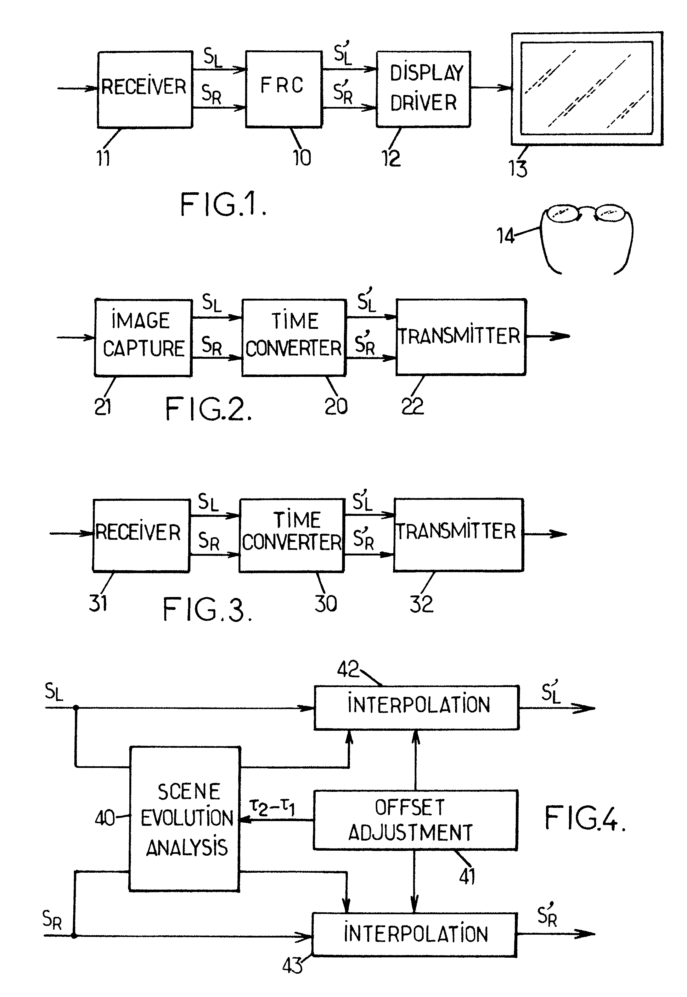
[0031]FIG. 1 shows a stereoscopic video signal processor 10 used in a TV set. The expression “TV set” as used herein is quite general and meant to also encompass video projectors and head-mounted stereoscopic displays. A receiver front end 11 receives the input stereoscopic video signal which has been transmitted in a suitable format over a communication medium. The communication medium referred to here may include a telecommunication network and / or a storage medium such as an optical disc (DVD, Blu-Ray, . . . ), a magnetic or solid state hard drive, a magnetic tape, etc.

[0032]In the embodiment shown in FIG. 1, the receiver 11 extracts a left-eye frame sequence SL and a right-eye frame sequence SR from the input stereoscopic video signal and supplies them to the input of the processor 10. The processor 10 can advantageously be a frame rate converter (FRC) processor provided in the TV set. The left-eye and right-eye frame sequences SL, SR are converted by the processor 10 and the con...


PUM


Abstract

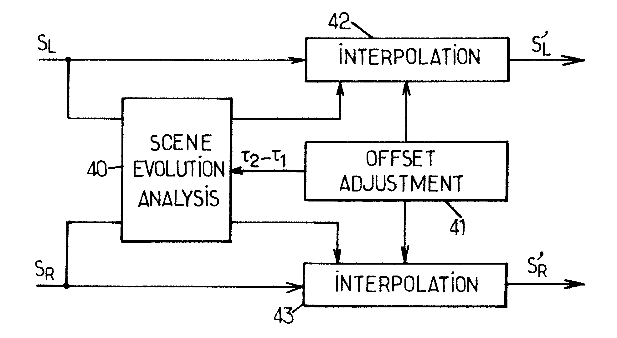
An input stereoscopic video signal has a first frame sequence (SL) in a left-eye channel and a second frame sequence (SR) in a right-eye channel, the second frame sequence (SR) having a zero or non-zero time offset τ1 with respect to the first frame sequence (SL). It is converted into an output stereoscopic video signal having a third frame sequence (S′L) in the left-eye channel and a fourth frame sequence (S′R) in the right-eye channel. The fourth frame sequence (S′R) has a zero or non-zero time offset τ2 with respect to the third left-eye frame sequence (S′L). The two time offsets τ1, τ2 may be different τ2≠τ1), in which case the conversion comprises a time interpolation of the frames of at least one of the first and second frame sequences with interpolation parameters selected to apply a relative time shift of τ2−τ1 to the right-eye channel with respect to the left-eye channel.

Description

BACKGROUND OF THE INVENTION[0001]The present invention relates to the processing of digital stereoscopic video signals with accurate rendering of three-dimensional (3D) effects.[0002]In the stereoscopic three-dimensional viewing of a scene, distinct but similar images are presented to the left and right eyes. Disparities between the observed left and right images act as depth cues to the human visual system (HVS), creating the illusion of depth in the perceived image when the HVS combines the left eye and right eye images in the visual cortex. Extending this idea to video, when a time varying sequence of left-eye images and right-eye images is rapidly presented with appropriate disparities between corresponding left-eye and right-eye images, an illusion of depth in a moving scene can be created.[0003]Various stereoscopic 3D display technologies exist, or can be envisaged, that present over a given time period a sequence of correlated image pairs to the left and right eyes.[0004]In s...

Claims


Application Information

Patent Timeline
Patent Type & Authority Patents(United States)
IPC IPC(8): H04N13/00H04N13/04
CPCH04N13/0029H04N13/0048H04N13/0497H04N13/139H04N13/161H04N13/398
Inventor SHAND, MARKETORRE, GUILLAUME
Owner ZORAN CORPORATION
Learn More