Establishing z-axis location of graphics plane in 3D video display

a technology of video display and graphics, applied in the direction of instruments, computing, electric digital data processing, etc., can solve problems such as not having an optimal positioning of graphics, and achieve the effect of reducing disparities

Inactive Publication Date: 2019-01-29
SATURN LICENSING LLC
View PDF28 Cites 0 Cited by
  • Summary
  • Abstract
  • Description
  • Claims
  • Application Information

AI Technical Summary

Benefits of technology

[0006]In example implementations, in response to the first command the processor increases a disparity between two identical images along an x-axis defined by the display. In response to the second command the processor decreases the disparity. The images defining the disparity may be video content images presented in a video plane of the device, or UI images presented in a graphics plane of the device. In any case, the first and second commands can cause the processor to cause the UI to appear to move incrementally in that the UI moves a fraction of a total distance available for movement of the UI along the z-axis responsive to a single command.

Problems solved by technology

As mentioned above, however, screen size differences and viewing location differences change the 3D effect and hence there is not an optimal positioning of the graphics in the “z” dimension, i.e., the new, third dimension toward and away from the surface of the display.

Method used


Image

  • Establishing z-axis location of graphics plane in 3D video display
  • Establishing z-axis location of graphics plane in 3D video display

Examples


Embodiment Construction

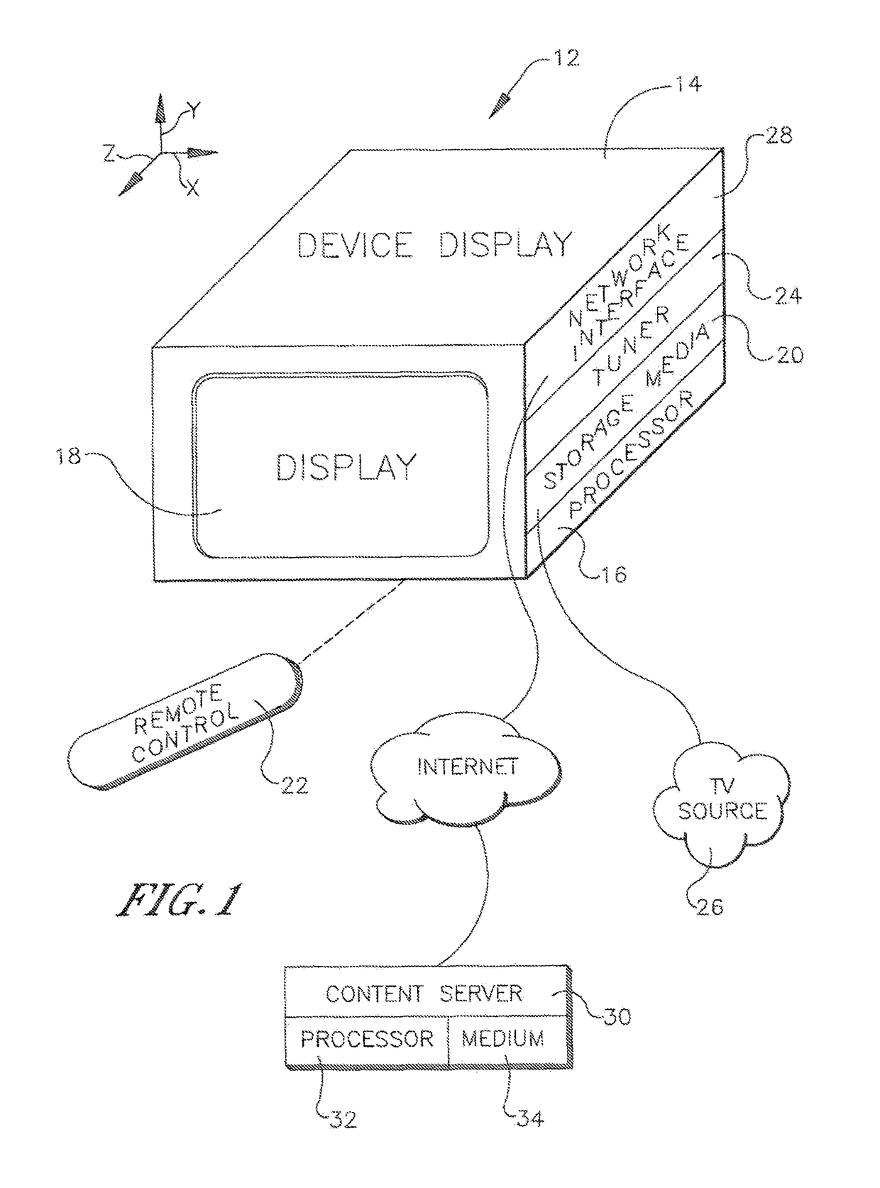
[0013]Referring initially to FIG. 1, a three dimensional (3D) video display device 12 such as a TV, game player, camera, personal digital assistant, laptop computer, personal computer (PC), etc. includes a housing 14 bearing a digital processor 16. The processor 16 can control a visual display 18 and an audible display such as one or more speakers. The processor 16 may access a media player module such that the device 12 has media decoding capability.

[0014]To undertake present principles, the processor 16 may access one or more computer readable storage media 20 such as but not limited to RAM-based storage, a chip implementing dynamic random access memory (DRAM)) or flash memory or disk storage. Software code implementing present logic executable by the device 12 may be stored on one of the memories shown to undertake present principles.

[0015]The processor 16 can receive user input signals from various input devices, including a wireless remote control (RC) 22, a point and click dev...


PUM


Abstract

A television for presenting video content in 3D has a video display controlled by a processor to present video content in a video plane and a user interface (UI) in a graphics plane. The processor receives input indicating a viewer desire to virtually move the UI up or back along a z-axis that is perpendicular to the video plane and responsive to the input change the location of the UI on the z-axis. This may done by altering image disparity produced to create a 3D effect.

Description

I. FIELD OF THE INVENTION[0001]The present application relates generally to establishing the z-axis location of a graphics presentation in a three dimensional (3D) video display.II. BACKGROUND OF THE INVENTION[0002]3D video such as 3D television is a fast growing technical field. Currently, 3D video is established by presenting two simultaneous views of the same video content marginally offset from each other on the horizontal (“x”) axis. The offset may be thought of as a horizontal disparity. The larger the display, the larger the possible horizontal disparity, with a larger disparity producing a more pronounced 3D effect. Viewing a 3D display from a close distance also makes the 3D effect more pronounced than viewing the display from afar.[0003]Because video viewers expect control enhancements such as user interfaces, menus, and the like to carry over to 3D from 2D, 3D video presentation devices must provide, in addition to 3D content, the capability to overlay graphics onto the v...

Claims


Application Information

Patent Timeline
Patent Type & Authority Patents(United States)
IPC IPC(8): G06F3/0481H04N13/128G06T19/00G06F3/0483G06F3/0482H04N13/183
CPCH04N13/183H04N13/128
Inventor SHINTANI, PETER
Owner SATURN LICENSING LLC
Why Eureka
Try Eureka