Apparatus for applying a coating to the surface of cylindrical articles

a cylindrical object and apparatus technology, applied in the direction of coatings, spraying apparatus, liquid surface applicators, etc., can solve the problems of lack of degree of freedom of working members, cumbersome and unfitness of painting pipelines, and cumbersome devices, etc., to extend functional possibilities and improve technical characteristics.

Inactive Publication Date: 2017-06-06
KOYAVA OTARI VLADIMIROVICH
View PDF5 Cites 0 Cited by
  • Summary
  • Abstract
  • Description
  • Claims
  • Application Information

AI Technical Summary

Benefits of technology

[0008]The problem addressed by the claimed invention is that of creating a compact apparatus for applying a coating to the surface of pipes, the apparatus having improved technical characteristics and extended functional possibilities.
[0009]The technical results achieved as a result of carrying out the claimed invention consist in increasing efficiency of the apparatus, in simplifying the design and reducing the overall dimensions of the apparatus, and also in extending the functional possibilities, in particular by providing for the possibility of applying a coating to the surface of a cylindrical article at locations of a bend and at locations at which access is difficult, including when pipes are arranged at a close distance to facades of buildings or of other surfaces.
[0010]The technical results of the claimed invention achieved via offered apparatus for applying a coating to the surfaces of cylindrical articles which comprises: a detaching coating member comprising at least two rotating rollers having ability congruently annularly encompass the periphery of a cylindrical article to be treated; mechanism for detaching the coating member; a system for feeding the coating material into coating member. Each of the rollers is formed with an internal cavity and the walls are permeated by the coating material, where said rollers provide a flow of coating material from the inner cavity of the roller onto the treated surface, and have a passage for supplying the coating material into the inner cavity. The apparatus for applying a coating additionally comprises a roller rotary actuator, a carriage and at least two arcuate brackets movably joined to the carriage. The rollers are designed to be capable of bending easily in any direction and have high torsional stiffness and low bending stiffness. One end of each roller is rotatably fastened to the carriage and is connected by means of a spindle to the rotary actuator. The other end of each roller is rotatably fastened to the free end of an arcuate bracket. The brackets are mounted on the carriage with a distance therebetween sufficient to accommodate the cross-section of the article to be treated. The brackets are capable of rotating towards one another in a mutually perpendicular manner and of enclosing the cross-section of the cylindrical article in a semi-circular manner.
[0030]implementation of the rollers as easily be bent in any direction of flexible shafts, having great torsional stiffness and low bending;

Problems solved by technology

The device is characterized by cumbersome and not fit for painting pipelines closely located to the facades of buildings or placed close parallel pipelines or pipelines located in difficult access areas.
This known device is also characterized by cumbersome and not fit for processing pipelines located in places of difficult access.
The disadvantage of this device is the lack of degrees of freedom of the working member, which prevents its use for the treatment of pipelines at locations of a bend, and low productivity due to the need to manually move the working member along the treated surface.
Furthermore, the device is also cumbersome and time consuming to manufacture.

Method used


Image

  • Apparatus for applying a coating to the surface of cylindrical articles
  • Apparatus for applying a coating to the surface of cylindrical articles
  • Apparatus for applying a coating to the surface of cylindrical articles

Examples


Embodiment Construction

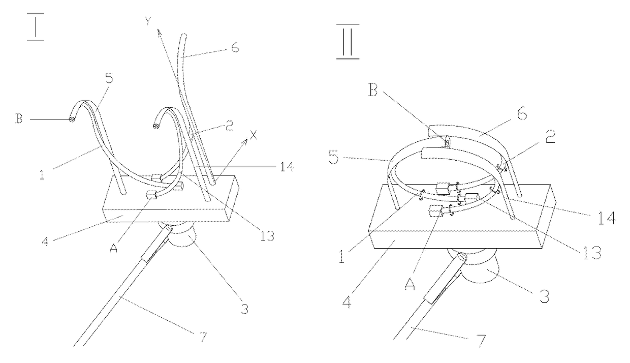
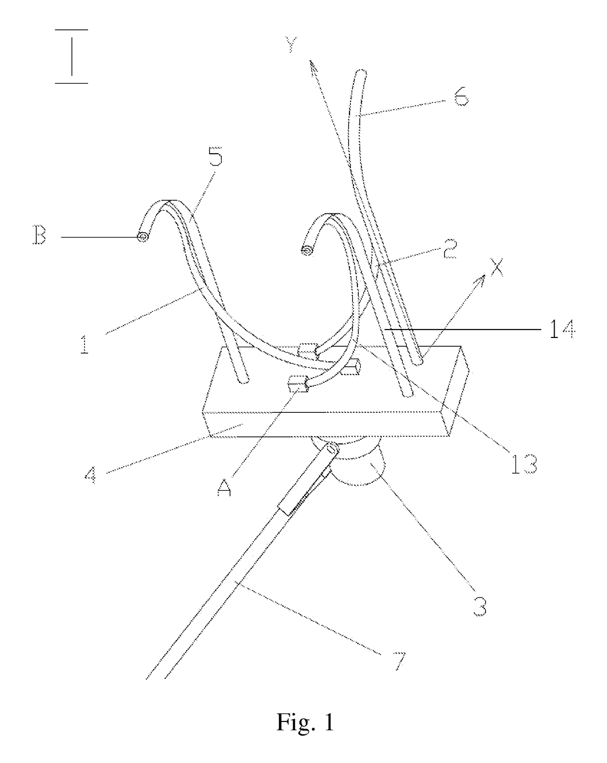
[0052]In a preferred embodiment apparatus for applying a coating to the surface of cylindrical articles comprises: detachable coating member comprising at least two rotatable rollers 1, 2; a roller rotation actuator 3; carriage 4 and at least two arcuate brackets 5, 6, movably joined to the carriage 4; telescoping pole 7, is pivotally attached to the carriage 4, or handle (not shown); a mechanism for detaching the coating member and feeding system in its of a coating material (not shown). The rollers 1 and 2 are designed to be capable of bending easily in any direction of flexible shafts and have high torsional stiffness and low bending stiffness and comprise an inner cavity 8, the duct 9 for supplying the coating material. The rollers 1, 2 having walls permeable to the coating material, ensure delivery the latter from the inner cavity of the roller to the treated surface for example through the holes 10. One end (A) of each of the rolls 1, 2 is rotatably mounted, for example, in be...


PUM

PropertyMeasurementUnit
torsional stiffnessaaaaaaaaaa
bending stiffnessaaaaaaaaaa
distanceaaaaaaaaaa

Abstract

The invention relates to apparatuses for treating the outside surface of cylindrical articles, and can be used for applying liquid substances to the surface of such articles. The apparatus for applying a coating additionally comprises a roller rotation actuator, a carriage and at least two arcuate brackets movably joined to the carriage. The rollers are designed to be capable of bending easily in any direction and have high torsional stiffness and low bending stiffness. One end of each roller is rotatably fastened to the carriage and is connected by a spindle to the rotation actuator. The other end of each roller is rotatably fastened to the free end of an arcuate bracket. The brackets are mounted on the carriage with a distance therebetween sufficient to accommodate the cross-section of the article to be treated. The brackets are capable of rotating towards one another in a mutually perpendicular manner and of enclosing the cross-section of the cylindrical article in a semi-circular manner. The technical result of the invention is increased efficiency, a simplified design, reduced dimensions and greater functional capabilities.

Description

BACKGROUND OF THE INVENTION[0001]Field of the Invention[0002]The invention relates to apparatuses for treating the external surface of cylindrical articles, for example, pipes, during the construction and reconstruction thereof, and can be used for applying a coating to the surface of cylindrical articles, in particular, for applying liquid substances—varnishes, paints, glues, solvents and bitumen-based coatings, etc. Furthermore, the cylindrical article can have a definitive length, or can be part of a pipe.[0003]Description of the Related Art[0004]Various devices are known that are used for coating the surface of cylindrical articles.[0005]A known device for applying coating to the pipes containing a reservoir for liquid substances mounted on tapered rollers, where its working member is in the form of interconnected sidewall split rings with porous elements circumferentially encompassing the painted pipe joined by the branch pipe with a reservoir for coloring liquid. (USSR Invento...

Claims


Application Information

Patent Timeline
Patent Type & Authority Patents(United States)
IPC IPC(8): B05C1/08B05B13/04B05C5/02B05C1/10
CPCB05C1/0821B05B13/0436B05C1/10B05C5/0241Y10S118/11Y10S118/13
Inventor KOYAVA, OTARI VLADIMIROVICH
Owner KOYAVA OTARI VLADIMIROVICH
Why Eureka
Try Eureka