
Open-end spinning rotor

a technology of open-end spinning rotor and rotor shaft, which is applied in the direction of open-end spinning machines, mechanically actuated clutches, mechanical apparatus, etc., can solve the problems of damage to the drive and/or the mounting of the spinning rotor, the inability to play-free connection of this type, and the inability to exchange open-end spinning rotors. the effect of easy exchange and reliable centering of the rotor cup and the rotor sha

Active Publication Date: 2017-06-06
SAURER SPINNING SOLUTIONS GMBH & CO KG
View PDF24 Cites 0 Cited by
  • Summary
  • Abstract
  • Description
  • Claims
  • Application Information

AI Technical Summary

Benefits of technology

[0006]It is therefore an object of the present invention to develop the spinning rotor in such a way that the rotor cup can easily be exchanged and a reliable centering of the rotor cup and rotor shaft is simultaneously achieved.
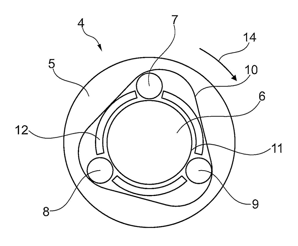
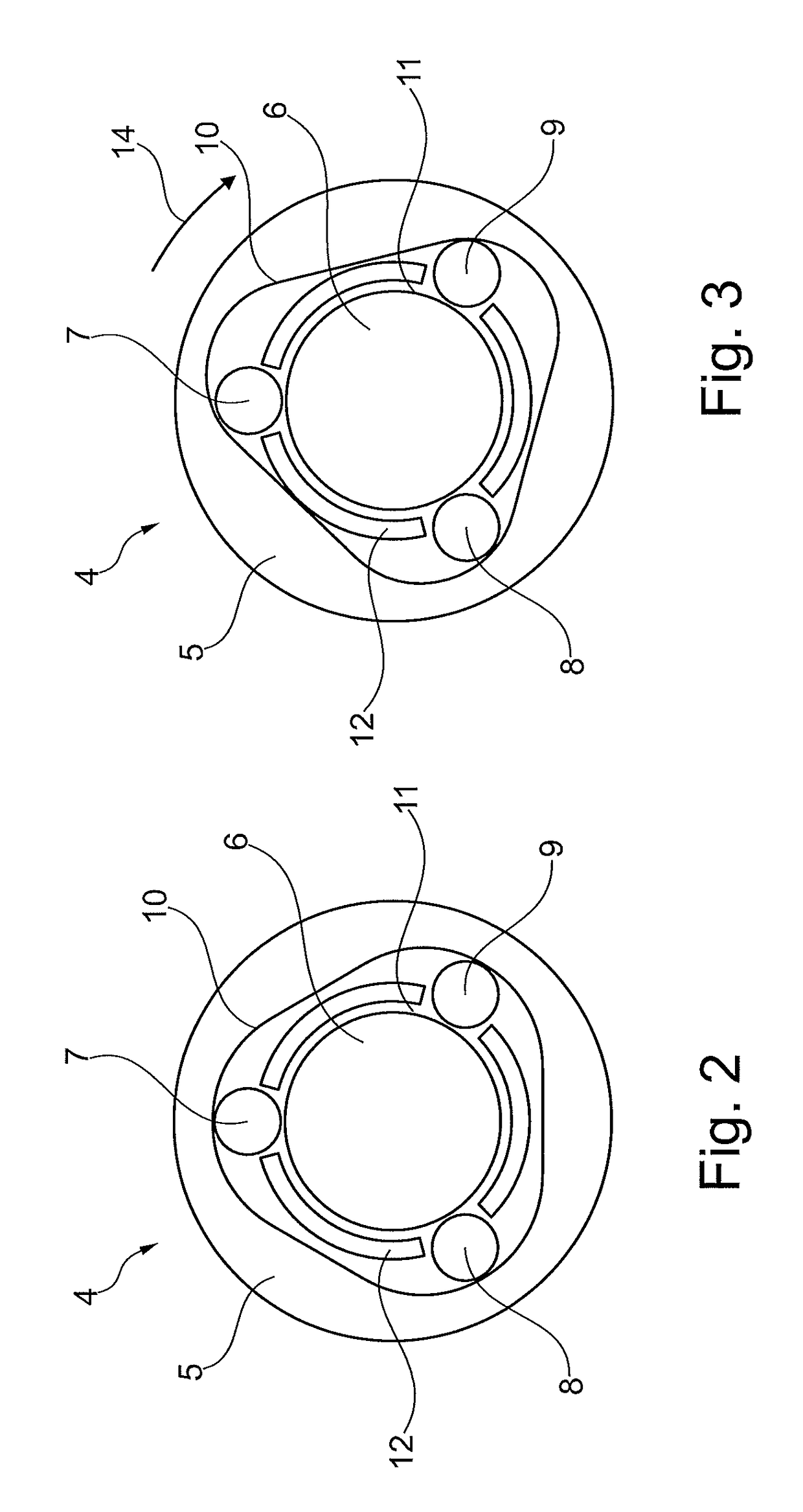
[0008]A reliable centering of the rotor cup takes place owing to the coupling device according to the invention, and easy exchangeability of the rotor cup is simultaneously ensured. In order to achieve this, the centering firstly takes place when the spinning rotor is started up, or expressed differently, by the driving of the rotor shaft. In the rest state of the spinning rotor, in other words, when the rotor shaft is not driven, the axle element of the rotor cup can easily be displaced in relation to the receiving element of the rotor shaft. The contour of the receiving element, the contour of the axle element and the clamping bodies are configured in such a way that there is a position, in which the clamping bodies have adequate play between the contour of the receiving element and the contour of the axle element. The clamping bodies are arranged so as to be movable at least to a limited extent so that the system of the axle element, receiving element and clamping bodies can be centred when the rotor shaft is driven. The mode of action is based here on the inertia of the rotor cup. As the receiving element, the axle element and the clamping bodies are not rigidly connected to one another, the clamping bodies and the axle element remain in their rest state for a brief moment when the rotor shaft is started up. As a result, the relative rotational movement between the receiving element on the one hand and the clamping bodies and the axle element on the other hand is produced. As soon as the clamping bodies are clamped between the contour of the receiving element and the contour of the axle element, the connection is absolutely free of play. The clamping state is thus securely maintained and therefore so is the non-positive transmission of the drive torque from the rotor shaft to the rotor cup as long as the rotor shaft is driven. Once the spinning rotor has been braked and passes back into the rest state, the clamping state is released by itself and the clamping can easily be eliminated by minimal rotation of the rotor cup during the manual change of the rotor cup.
[0009]Advantageously, the contour of the receiving element, the contour of the axle element and the clamping bodies are configured in such a way that the clamping bodies are clamped between the contour of the receiving element and the contour of the axle element independently of the drive direction of the rotor shaft when the rotor shaft is driven. It is thus possible for the spinning rotor to be able to be driven in different directions depending on the desired yarn twist.

Problems solved by technology

Depending on the type of mounting, it may make the change of open-end spinning rotors more difficult or even impossible if the rotor cup and the rotor shaft are non-releasably connected to one another.
A play-free connection of this type is not possible, however, because of the manufacturing tolerances always present.
However, even with a small amount of play within the range of a few hundredths of millimeters, imbalance forces may be produced at the high rotational speeds, at which the spinning rotor rotates, which can damage the drive and / or the mounting of the spinning rotor.
The imbalance is produced here by the axial offset between the rotor cup and rotor shaft.

Method used


Image

  • Open-end spinning rotor
  • Open-end spinning rotor
  • Open-end spinning rotor

Examples


Embodiment Construction

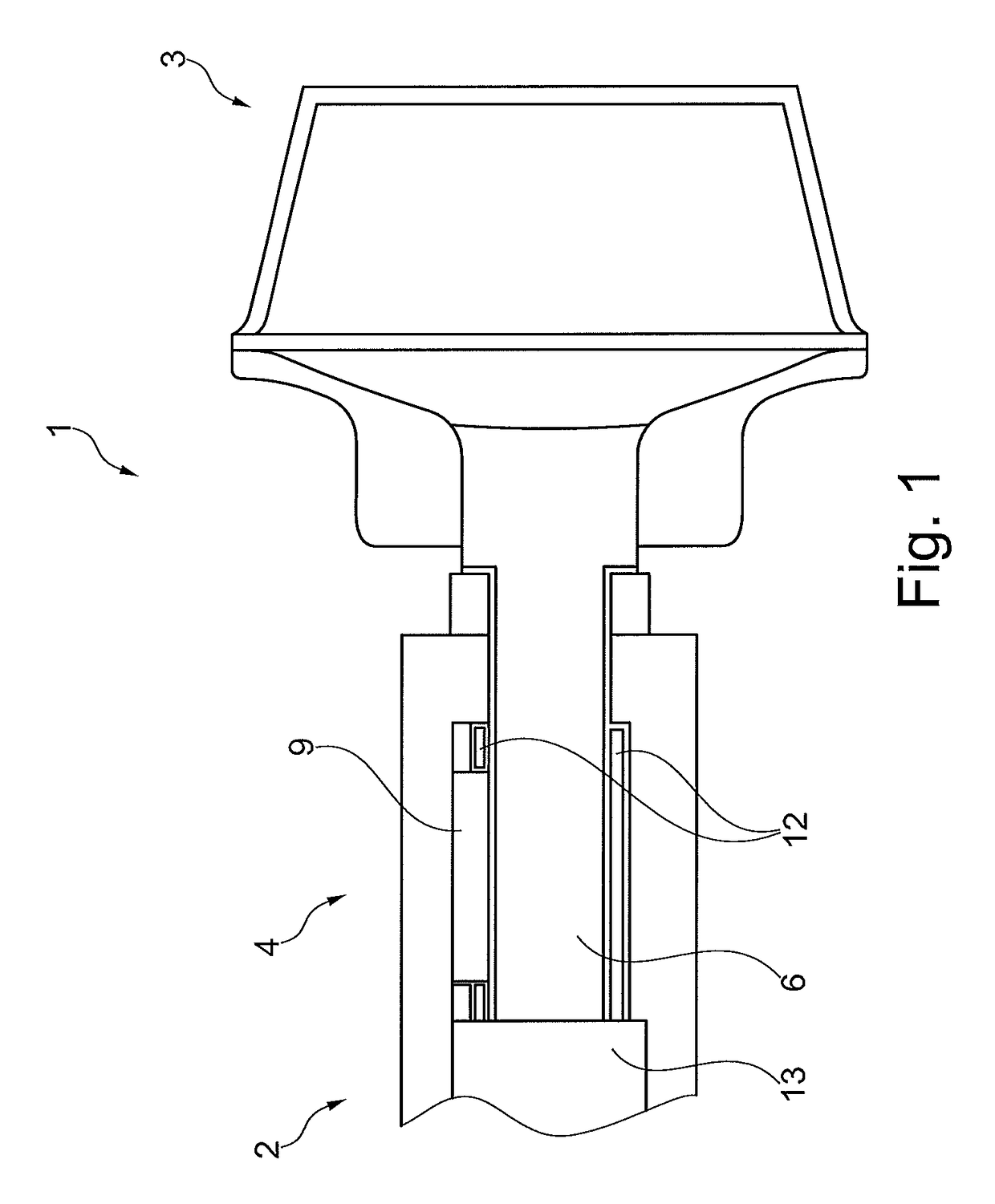
[0019]FIG. 1 shows an open-end spinning rotor 1 according to the invention. The open-end spinning rotor 1 has a rotor shaft 2. The rotor shaft 2 is driven by a drive device, not shown, preferably a single drive. The rotor cup 3 is releasably connected to the rotor shaft 2 by means of a coupling device 4. The rotor cup 3 can thus be exchanged in the case of wear or to spin a different type of yarn.

[0020]In the sectional view in FIG. 2, the coupling device 4 is shown in more detail. The coupling device 4 has a receiving element 5, an axle element 6 and three clamping bodies 7, 8, 9 configured as rolling bodies. In this case, the receiving element 5 is rigidly connected to the rotor shaft 2. The rotor shaft 2 and receiving element 5 may be configured in one piece here as one component or the receiving element 5 can be connected as an insert by a press fit to the rotor shaft 2. Accordingly, the axle element 6 is rigidly connected to the rotor cup 3. The clamping bodies 7, 8, 9 are arran...


PUM

PropertyMeasurementUnit
angleaaaaaaaaaa
drive torqueaaaaaaaaaa
rotational speedsaaaaaaaaaa

Abstract

An open-end spinning rotor (1), comprising a rotor shaft (2), a rotor cup (3) and a coupling device (4) with a receiving element (5) connected to the rotor shaft (2) and an axle element (6) connected to the rotor cup (3). The coupling device (4) comprises three clamping bodies (7, 8, 9), arranged between a contour (10) of the receiving element and a contour (11) of the axle element. The contour of the receiving element, the contour of the axle element and the clamping bodies are configured such that by driving the rotor shaft, a relative rotational movement is produced between the receiving element and the clamping bodies and the axle element, in that owing to the relative rotational movement, the clamping bodies are clamped between the contour of the axle element and the contour of the receiving element to non-positively transmit a drive torque.

Description

CROSS REFERENCE TO RELATED APPLICATIONS[0001]This application claims the benefit of German patent application DE 10 2014 002 102.5, filed Feb. 15, 2014, herein incorporated by reference.FIELD OF THE INVENTION[0002]The present invention relates to an open-end spinning rotor, more particularly an open-end spinning rotor comprising a rotor shaft, a rotor cup and a coupling device, which releasably connects the rotor shaft and the rotor cup and has a receiving element connected to the rotor shaft and an axle element connected to the rotor cup.BACKGROUND OF THE INVENTION[0003]Spinning rotors used in open-end spinning machines, if necessary, for example in the case of wear or in order to manufacture a different type of yarn on the rotor-spinning machine, have to be able to be changed. Depending on the type of mounting, it may make the change of open-end spinning rotors more difficult or even impossible if the rotor cup and the rotor shaft are non-releasably connected to one another. There...

Claims


Application Information

Patent Timeline
Patent Type & Authority Patents(United States)
IPC IPC(8): D01H4/10
CPCD01H4/10F16D15/00F16D41/067F16D41/105
Inventor WASSENHOVEN, HEINZ-GEORG
Owner SAURER SPINNING SOLUTIONS GMBH & CO KG
Learn More