Dust collecting mechanism for groove machining head and groove machining apparatus

a technology of grinding head and grinding machine, which is applied in the direction of metal-working machine components, manufacturing tools, and working accessories, etc., can solve the problems of dust removal, rotating the fan, and damaging the surface of the substrate, so as to eliminate the risk of dust mixture entering the tool holder

Inactive Publication Date: 2017-06-06
MITSUBOSHI DIAMOND IND CO LTD
View PDF19 Cites 2 Cited by
  • Summary
  • Abstract
  • Description
  • Claims
  • Application Information

AI Technical Summary

Benefits of technology

[0008]The present invention intends to provide a dust collecting mechanism for groove machining head capable of effectively removing dust produced by scribing before attachment of the dust to the surface of a substrate, and a groove machining apparatus using the dust collecting mechanism.
[0014]According to the present invention having such features, the dust collecting hood attaches to the lower part of the groove machining head, and sucks dust produced near the tool at the time of scribing. Doing so can result in an effect making it possible to suck and remove dust before attachment of the dust to a thin film solar cell substrate or the like to perform groove machining without damaging the surface of the substrate. Also, arranging the frame-shaped partition set on the bottom plate at a fixed distance from the tool holder results in an effect that when sucking dust through the duct, causes air flow from the side of the tool holder toward the tip of the tool to eliminate the risk of the mixture of dust into the tool holder.

Problems solved by technology

In the process of the scribing, once the dust attaches to a thin film solar cell substrate, there arises a problem of the difficulty to remove the dust, or even in the case of successfully removing the dust, damaging the surface of the substrate.
Further, although the dust collecting device in JPA-Hei9-285939 has a suction head adapted to suck dust around a rotary tool, rotating the fan gives arise to a problem of complicated structure.

Method used


Image

  • Dust collecting mechanism for groove machining head and groove machining apparatus
  • Dust collecting mechanism for groove machining head and groove machining apparatus
  • Dust collecting mechanism for groove machining head and groove machining apparatus

Examples


Embodiment Construction

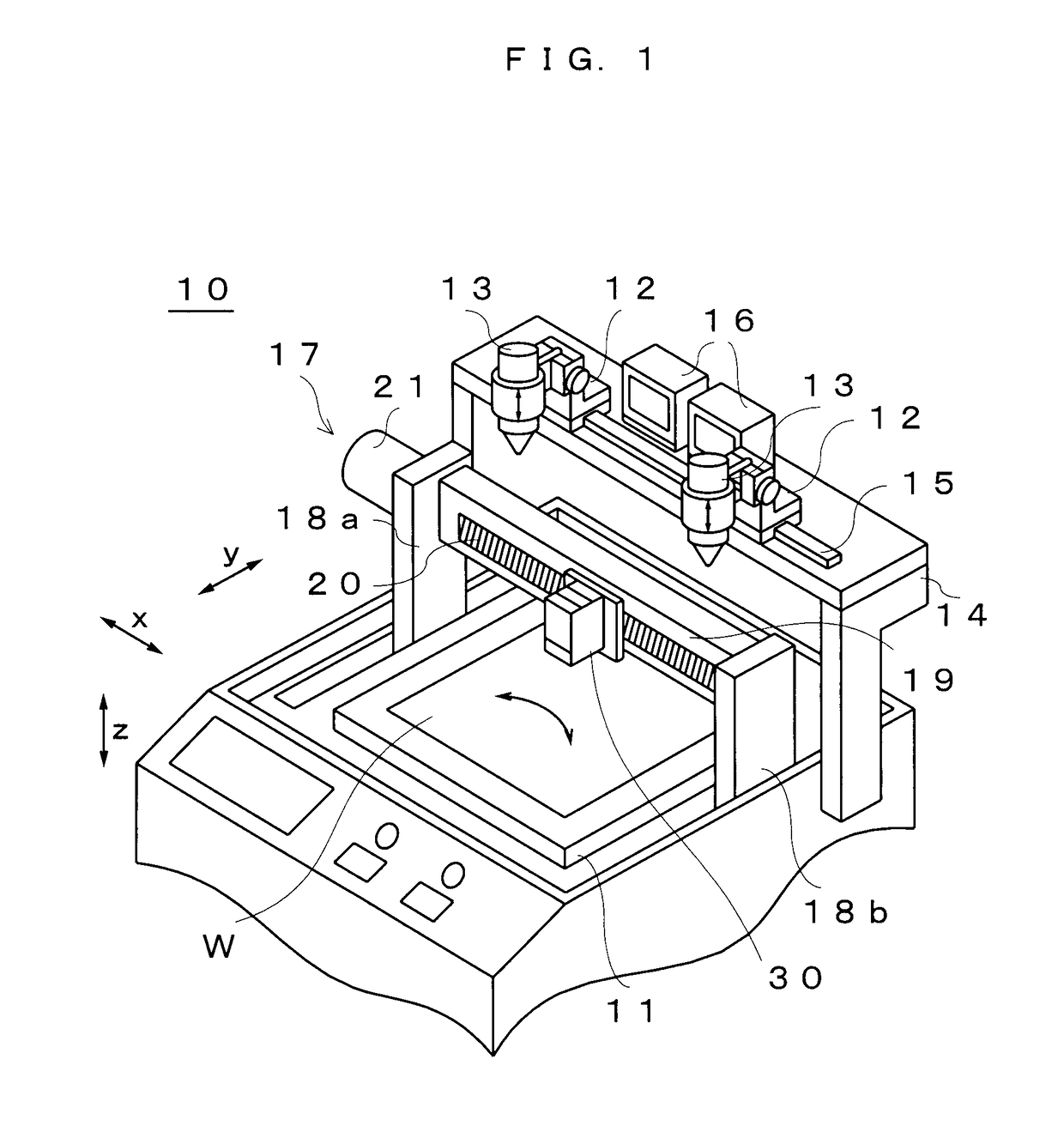
[0026]FIG. 1 is a perspective view illustrating an overall configuration of a groove machining apparatus according to embodiments of the present invention. In this view, the groove machining apparatus 10 includes a table 11 that places a thin film solar cell substrate W serving as a machining target on an xy plane thereof. The table 11 is movable in a y direction in FIG. 1 in the horizontal plane (xy plane), and also rotatable at an arbitrary angle in the horizontal plane.

[0027]Above the table 11, cameras 13 respectively attach to two bases 12. Each of the bases 12 is movable along a guide 15 extending in an x direction on a supporting base 14. The two cameras 13 are movable up and down, and monitors 16 respectively display corresponding images photographed by the cameras 13.

[0028]A bridge 17 provided above the table 11 has a pair of supporting columns 18a and 18b, a guide bar 19 provided between the supporting columns in the x axis direction, and a motor 21 adapted to drive a guide...


PUM

PropertyMeasurementUnit
distanceaaaaaaaaaa
brittleaaaaaaaaaa
transparent conductiveaaaaaaaaaa

Abstract

A groove machining head has a dust collecting hood 40 having a suction port in the vicinity where tools 32 protrude from a bottom plate 33 of the groove machining head. When performing groove machining on a substrate W using the groove machining head 30, a blower 35 sucks air inside the dust collecting hood 40 through ducts 34. Doing so can suck dust produced by the groove machining through the suction port of the dust collecting hood 40 before attachment of the dust on the substrate W.

Description

BACKGROUND OF THE INVENTION[0001]1. Field of the Invention[0002]The present invention relates to dust collecting mechanism for a groove machining head collecting dust produced when performing groove machining on a thin film, such as when manufacturing thin film solar cells or other devices, and to a groove machining apparatus.[0003]2. Discussion of the Related Art[0004]A manufacturing process for an integrated solar cell includes steps of stacking semiconductor thin films on a substrate and repeating patterning multiple time as described in, for example, Japanese Unexamined Patent Publication JPA2005-191167. This manufacturing process includes forming a metallic lower electrode layer on the brittle material substrate, and as a patterning P1, cutting and dividing the electrode layer into rectangles using a laser beam. Then, forming a P-type light absorption layer and a buffer layer on the patterned electrode layer gives an integrated semiconductor thin film. After that, as a patterni...

Claims


Application Information

Patent Timeline
Patent Type & Authority Patents(United States)
IPC IPC(8): H01L21/67B28D7/02
CPCH01L21/67092B28D7/02Y10T83/207B23Q11/0046
Inventor KATAGIRI, NAOKI
Owner MITSUBOSHI DIAMOND IND CO LTD
Why Eureka
Try Eureka