Image sensor assembly for removing dust from a surface of an image sensor

a technology of image sensor and assembly, which is applied in the field of image sensor assembly, can solve the problems of bad affecting the quality of captured images, and achieve the effects of effective removal of dust sticking to the surface, easy disassembly and assembly, and small structur

Inactive Publication Date: 2015-05-26
SAMSUNG ELECTRONICS CO LTD
View PDF15 Cites 2 Cited by
  • Summary
  • Abstract
  • Description
  • Claims
  • Application Information

AI Technical Summary

Benefits of technology

[0004]Various embodiments of the invention provide an image sensor assembly capable of effectively removing dust sticking onto a surface of an image sensor; provide an image sensor assembly which can be manufactured to have a simple, small, and light structure and a dust removal function; provide an image sensor assembly which can be easily disassembled and assembled and have a dust removal function; and provide an image sensor assembly which can vibrate a vibrator to effectively remove dust and stably maintain combination states of components even when the vibrator repeatedly vibrates.

Problems solved by technology

Such an image sensor corresponds to a film of a conventional analog camera, and dust or the like sticking onto a surface of the image sensor may badly affect a quality of a captured image.

Method used


Image

  • Image sensor assembly for removing dust from a surface of an image sensor
  • Image sensor assembly for removing dust from a surface of an image sensor
  • Image sensor assembly for removing dust from a surface of an image sensor

Examples


Embodiment Construction

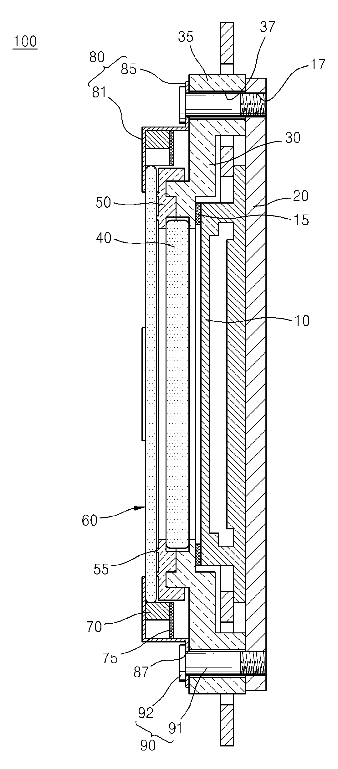
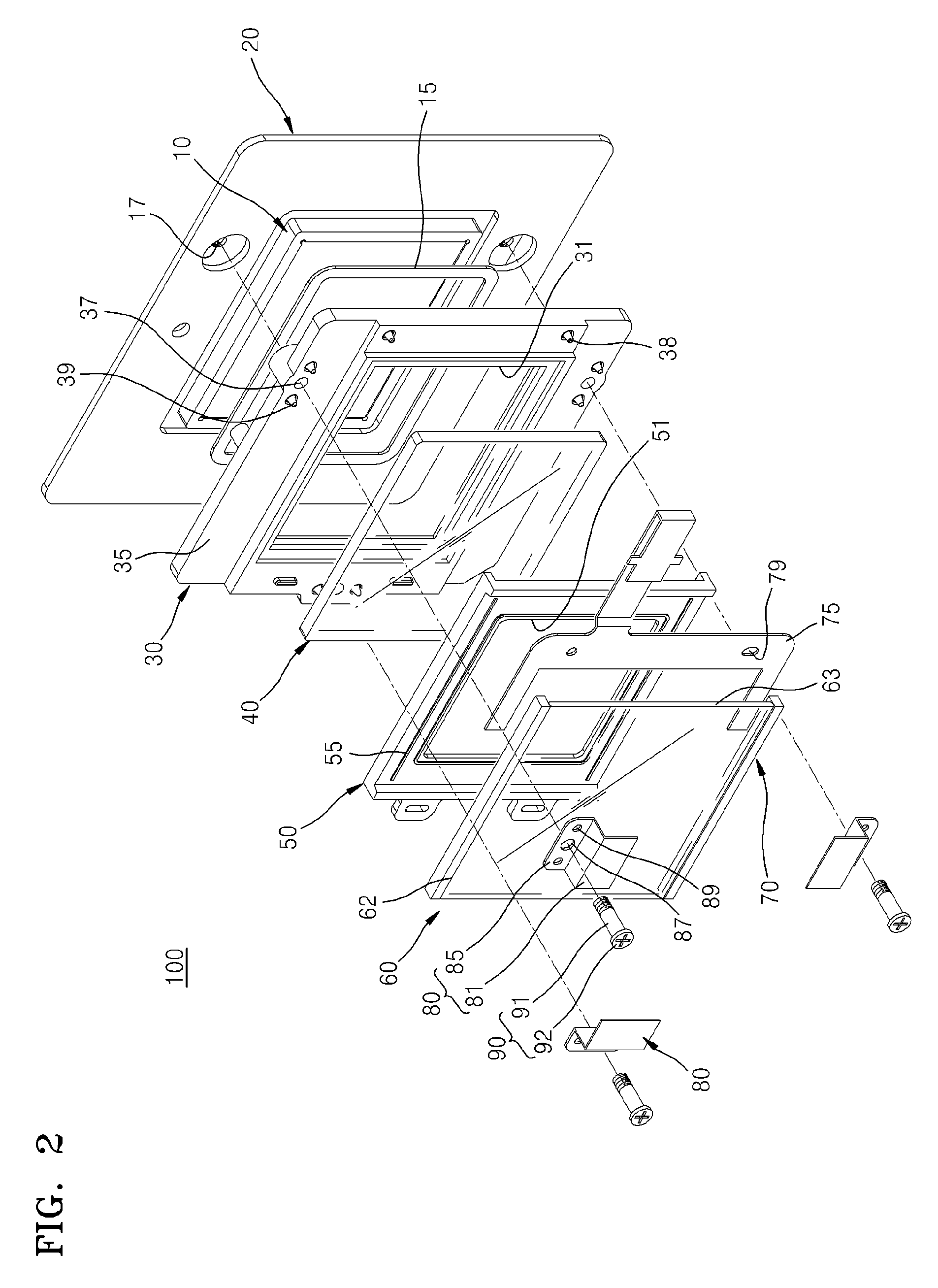
[0022]Structure and operation of an image sensor assembly according to various embodiments of the invention will now be described in detail with reference to the attached drawings.

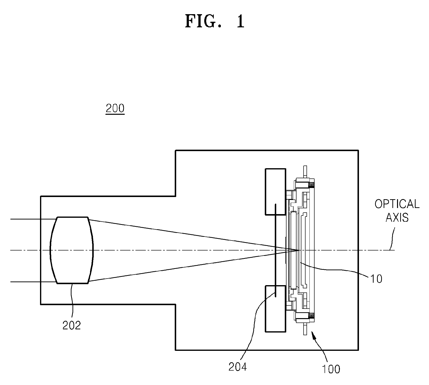
[0023]FIG. 1 is a schematic view horizontally illustrating a digital photographing apparatus 200 including an image sensor assembly 100, according to an embodiment of the invention.

[0024]Referring to FIG. 1, the image sensor assembly 100 included in the digital photographing apparatus 200 includes an image sensor. The digital photographing apparatus 200 includes a lens unit 202 and the image sensor assembly 100 which is disposed opposite to a subject focused on the lens unit 202.

[0025]The image sensor 10 of the image sensor assembly 100 captures an image of the subject and converts the image into an electric signal. The image sensor 10 may be a photoelectric conversion element, such as a charge-coupled device (CCD) or a complementary metal-oxide-semiconductor (CMOS). The image of the subject is formed on a...


PUM


Abstract

An image sensor assembly includes: an image sensor; a support plate disposed on a back surface of the image sensor; a first frame which includes a first hole which is open allowing incident light onto the image sensor and is disposed on a front surface of the support plate to enclose at least a side edge of the image sensor; an optical filter disposed in the first hole to block a part of the incident light; a second frame which includes a second hole which is open to allow light to be incident onto the optical filter and is disposed in front of the first frame; a front plate which is disposed in front of the second hole to contact a front surface of at least a side edge of the second frame; and a vibrator which is combined with at least a side edge of the front plate.

Description

CROSS-REFERENCE TO RELATED PATENT APPLICATION[0001]This application is a continuation of U.S. patent application Ser. No. 13 / 150,463, filed Jun. 1, 2011, which claims the priority benefit of Korean Patent Application No. 10-2010-0083705, filed on Aug. 27, 2010, in the Korean Intellectual Property Office, the disclosure of which is incorporated herein in its entirety by reference.BACKGROUND[0002]The invention relates to an image sensor assembly, and more particularly, to an image sensor assembly capable of effectively removing dust or the like sticking onto a surface of an image sensor.[0003]An image sensor, such as a charge-coupled device (CCD) sensor, a complementary metal-oxide-semiconductor (CMOS) sensor, or the like, is installed in a digital image photographing apparatus, such as a digital camera, a digital camcorder, or the like. The image sensor is for capturing an image. Such an image sensor corresponds to a film of a conventional analog camera, and dust or the like sticking...

Claims


Application Information

Patent Timeline
Patent Type & Authority Patents(United States)
IPC IPC(8): H04N5/225H04N5/217
CPCH04N5/2253H04N5/2171H04N5/2254G03B2217/002H04N23/811H04N23/52H04N23/55H04N23/57H04N23/54
Inventor JI, EUN-HOHWANG, CHI-HUN
Owner SAMSUNG ELECTRONICS CO LTD
Why Eureka
Try Eureka